Breading machine and methods of operation

a breading machine and breading technology, applied in the field of food processing equipment and methods, can solve the problems of large dust, clogging of large openings with japanese style crumbs, and hammering the free flow of breading material, and achieve the effect of simplifying the loading of coating material

Inactive Publication Date: 2006-07-20
MP EQUIP
View PDF64 Cites 22 Cited by
  • Summary
  • Abstract
  • Description
  • Claims
  • Application Information

AI Technical Summary

Benefits of technology

[0015] An embodiment of the present invention comprises a breading machine for dispensing a coating material onto food products. The breading machine includes an enclosure defining a breading chamber, and a conveyor to move the food products through the breading chamber. The breading machine may also include a side-mounted feed hopper for simplified loading the coating material into the breading chamber and onto a lower return path of the conveyor means. Also included is a top-mounted hopper for receiving the coating material internally within the breading machine and for dispensing the coating material onto at least a top surface of the food products.

Problems solved by technology

For example, a flour type breading made of wheat or some other grain may have a tendency to pack or clog causing the material to bridge over transition spots within the breading machine.
Such bridging acts to hamper the free-flow of the breading material through the machine.
Japanese style crumbs tend to get clogged over larger openings than other common grain breading flours.
Over the years the coatings have turned more to spiced flour, which has required manufacturers of coating machines to redesign the machines to handle these flour type coatings, which are not considered to be free flowing.
Certain difficulties with respect to traditional breading machines also include loading the breading machine with the breading material, applying the breading material evenly over the food products, preventing clogging or bridging of the breading material within the breading machine, and eliminating clumping of the breading material within the breading machine.
However, such an arrangement causes significant dust, which is not desirable in the processing plant environment.
The arrangement also causes the top coating material to be applied at an angle and more coating is dispensed at the beginning portion of the cross conveyor, creating non-uniform coating across the width of the food product conveyor.
Additionally, the useful life of the conveyor belt within the top hopper is shortened by the fact that, in many cases, the top hopper is used as the main supply reserve and the heavy load put on the belt causes the belt to stretch and break.
It has been found that transferring coating material from auger to auger tends to be a problem and increases in difficulty as moisture builds up in the coating material.
High volumes and / or the type of breading material can therefore cause jams at the augers, requiring the machine to be stopped for cleaning of such jams, resulting in process down time.
Other problems with known breading machines relate to the need for a belt tensioning system for the food product conveyor, to the belt to be set correctly depending on the loading and speed of the belt.
However, this results in the breading machine effectively becoming longer, increasing the footprint on the plant floor, and making it more likely that the main belt may get tangled with other processing machinery in the processing line.
For safety, known breading machines typically have covers over the augers, but if a cover is opened, the auger is exposed, making accidents possible.
Newer machines may have safety cut outs or electronic devices that shut down the machine if a cover is opened, but such safety switches have proven not to be reliable and, in some cases, are rendered inoperative, which creates an even greater safety issue.
Although an auger guard may be used inside the cover, this presents problems when cleaning of the machine is necessary.

Method used


Image

  • Breading machine and methods of operation
  • Breading machine and methods of operation
  • Breading machine and methods of operation

Examples


Embodiment Construction

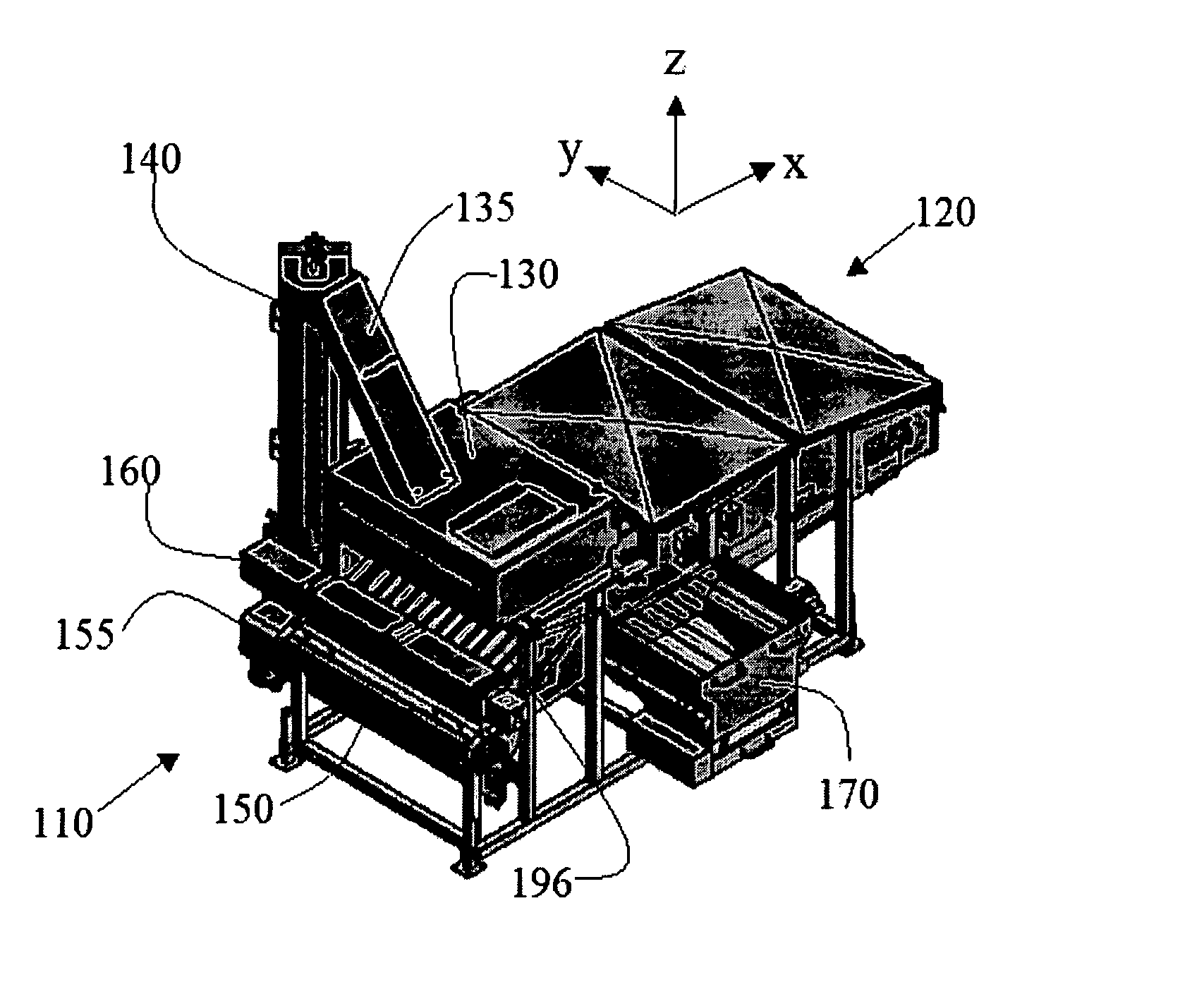
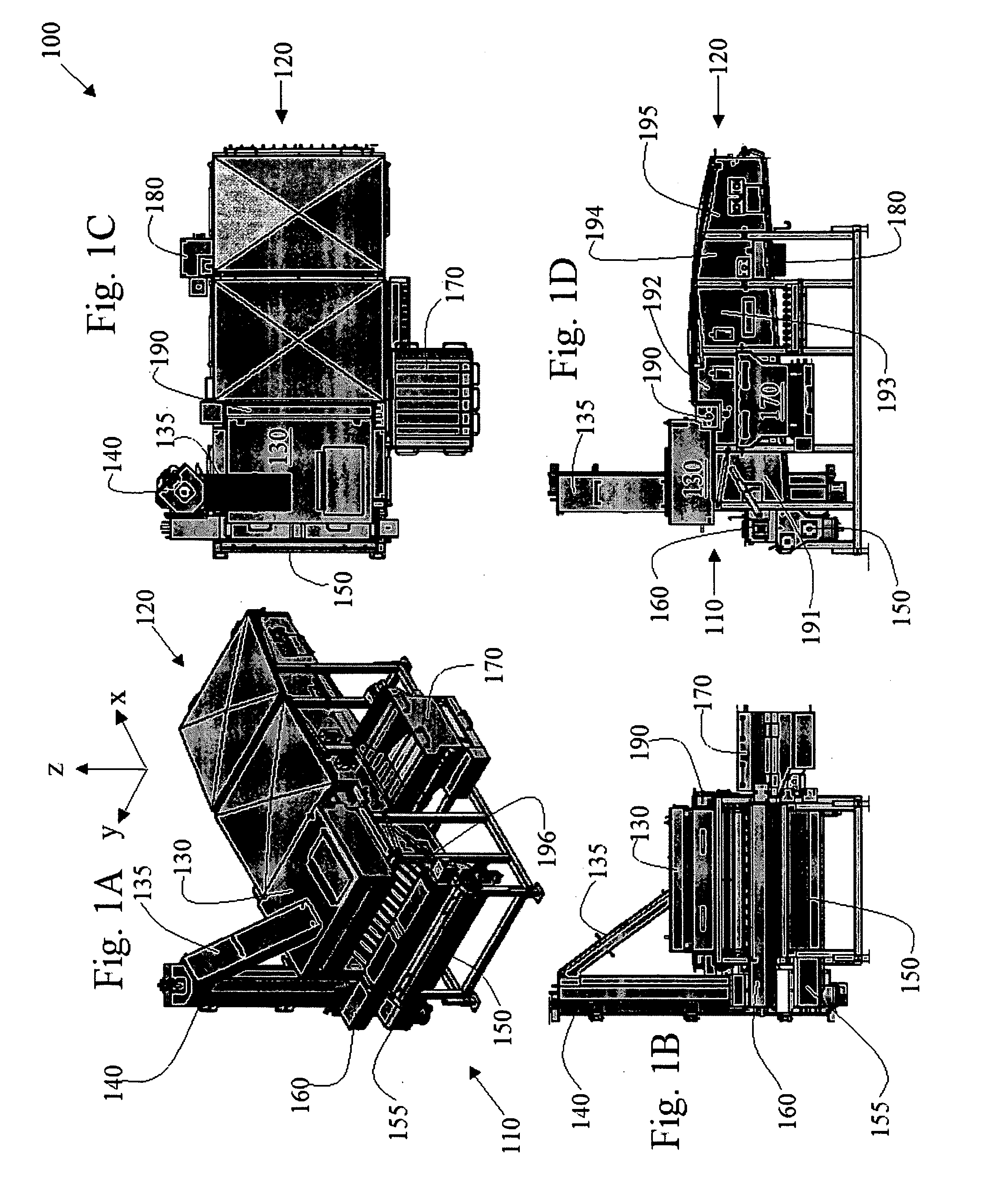
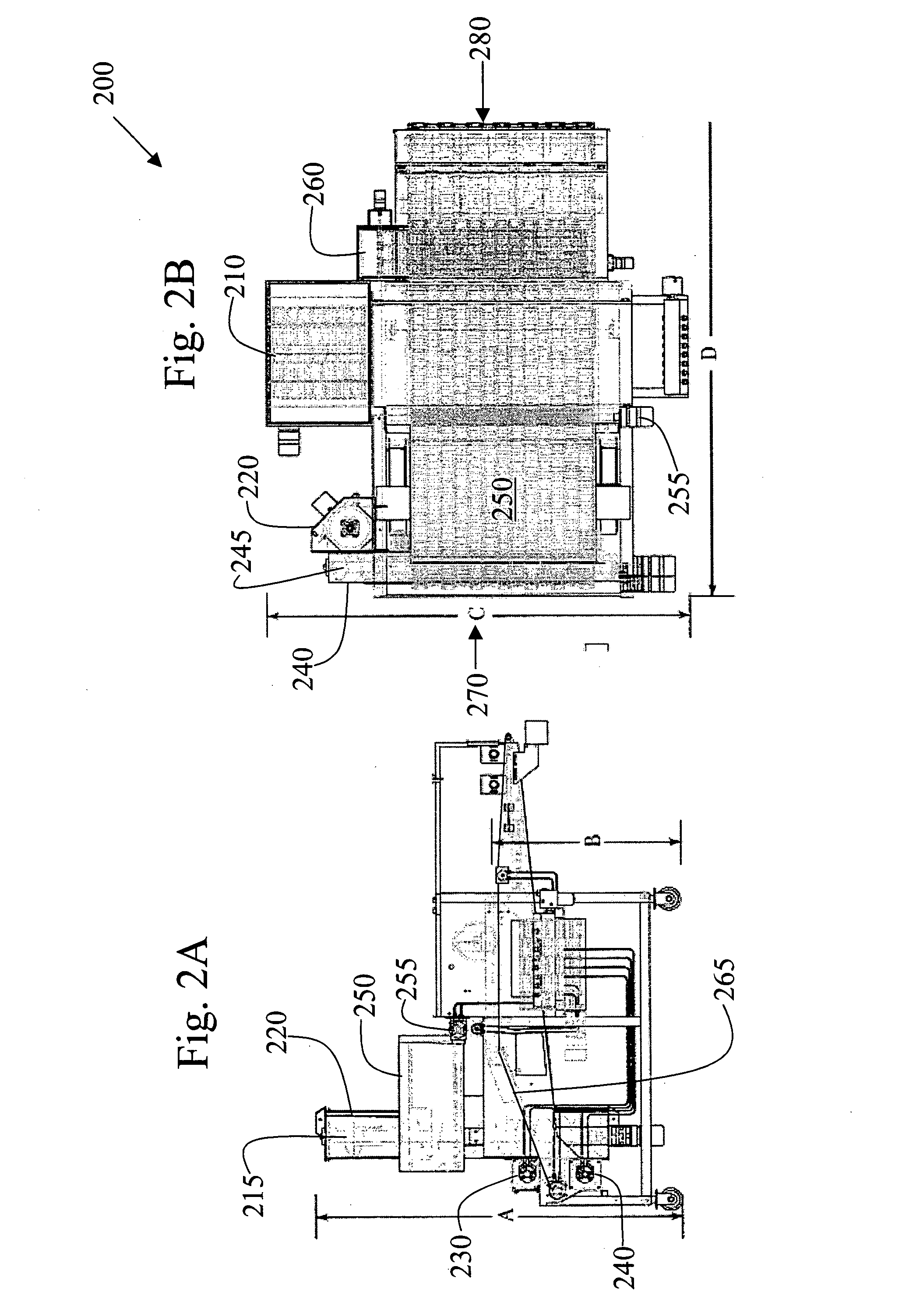
[0036]FIG. 1 illustrates several views of a first embodiment of a breading or coating machine 100. The breading machine 100 includes an input side 110 and an output side 120. Food products to be coated with a coating material (e.g., flour, bread crumbs, cracker meal) enter the breading machine 100 on the input side 110 and exit on the output side 120. The food products are typically fed into the input side 110 via a conveyor belt, for example, such as from prior equipment, such as a batter applicator. The food products are coated in the machine 100 and are typically fed out of the output side 120 and into, for example, a baking oven or fryer (not shown). The volumes of food products processed in this way are significant, and may be on the order of 10,000 pounds per hour or more, requiring significant amounts of coating materials, and distribution onto all of the food products passing therethrough in a uniform and desired manner. The breading characteristics desired for various food ...


PUM


Abstract

A breading machine, and improvements thereto, for use in high volume food production is disclosed. In accordance with an embodiment of the present invention, an improved breading machine includes a side-mounted feed hopper, a low pressure auger assembly including an auger transfer box with an input port for accepting a cross-feed screw and paddle, and an output port for transferring coating material to a vertical screw. The improved breading machine also includes a substantially cylindrical, rod-based spreader assembly and a transport conveyor belt for feeding the spreader assembly within a top hopper of the breading machine. The improved breading machine further includes a vibrating filter assembly to filter out clumps of coating material while allowing un-clumped material to be re-used within the breading machine.

Description

CROSS-REFERENCE TO RELATED APPLICATIONS / INCORPORATION BY REFERENCE [0001] Not applicable. TECHNICAL FIELD [0002] The present invention relates to food processing equipment and methods, for the coating or breading of food products. More particularly, certain embodiments of the present invention relate to a coating machine and methods for dispensing a coating material (e.g., flour, bread crumbs, cracker meal) onto food products, such as in large-scale food processing lines. BACKGROUND OF THE INVENTION [0003] In the industry of high volume production of food products, it is desirable to coat certain food products (e.g., chicken) with, for example, batter and a breading material before cooking the food products. Breading material may include a relatively dry material such as fine particle flour breading, Japanese-style breadcrumbs having a large distribution of bread crumb sizes, cracker meal of differing particle sizes, or many other types of coating materials. Each type of breading or...

Claims


Application Information

Patent Timeline
Patent Type & Authority Applications(United States)
IPC IPC(8): A23B4/02A23L35/00
CPCA23L1/005A23L1/3103A23P1/082A23L13/03A23P20/12
Inventor MATHER, DONALD A.JEONG, JASONCRAPPS, JOHNMATHER, SCOTT D.
Owner MP EQUIP
Why Eureka
Try Eureka