Apparatus and method for video decoding

Inactive Publication Date: 2006-07-13
NOVATEK MICROELECTRONICS CORP
View PDF1 Cites 4 Cited by
  • Summary
  • Abstract
  • Description
  • Claims
  • Application Information

AI Technical Summary

Benefits of technology

[0010] An object of the invention is to provide an apparatus and method for video decoding that decodes video with smaller buffers such that the cost is reduced and space is saved.
[0014] The apparatus and method for video decoding of the invention outputs the non-reference picture, which is not used as reference to decode other pictures, without storing it in full format, and therefore is able to effectively reduce the memory space occupied by the buffer and saves the space occupied by the memory.

Problems solved by technology

However, a very large storage space is required if one were to store the audio / video information in full format, especially the video data that records images.
However, the B picture itself cannot be used for other prediction encoding.
Nonetheless, the buffers in the conventional video decoding device 1 take up a relatively large memory space, and thereby the cost of video decoding devices cannot be lowered effectively.
In addition, buffering of the video bitstream, user information, on screen display (OSD) data and such would take up some memory space, and it is obvious that one 16Mb memory placed in the electronic product would not provide sufficient memory space.
On the other hand, replacing a 16Mb memory with one 32Mb or 64Mb memory would greatly increase the manufacturing cost of the video decoding device, and replacing it with two 16Mb memories would take up relatively more space besides the increase in cost, wherein the electronic product cannot be minimized in size effectively.

Method used


Image

  • Apparatus and method for video decoding
  • Apparatus and method for video decoding
  • Apparatus and method for video decoding

Examples


Embodiment Construction

[0020] The apparatus and method for video decoding according to preferred embodiments of the invention is described in reference to related drawings; the substantially same elements are given the same reference numerals.

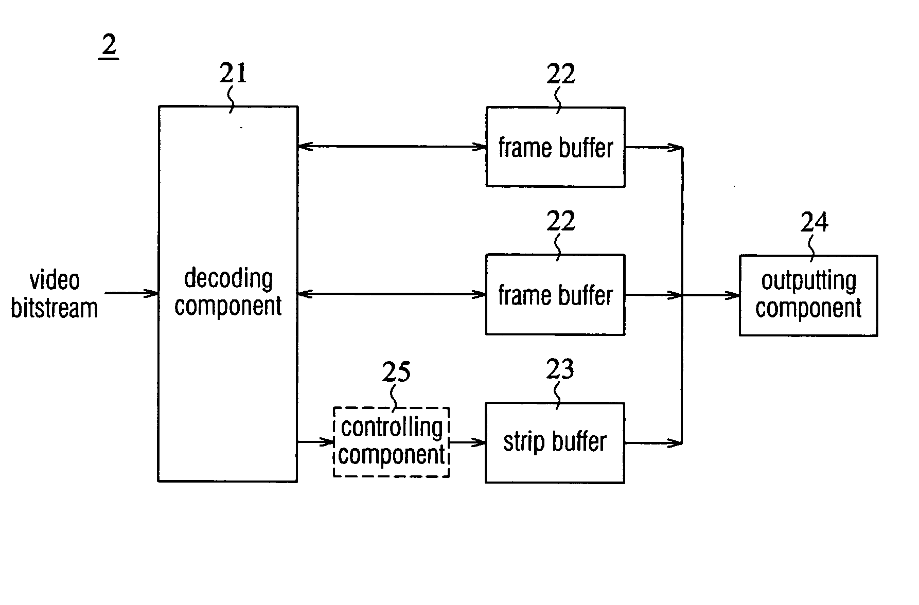
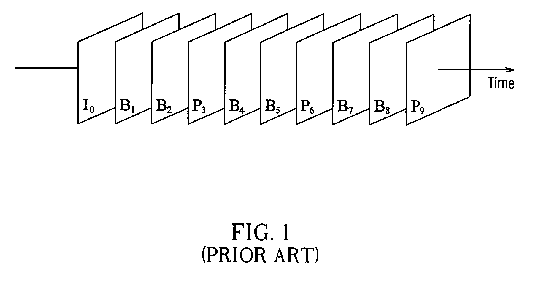
[0021] A preferred embodiment of an apparatus for video decoding 2 according to the invention is shown in FIG. 3, and the apparatus 2 is described by decoding the sequence illustrated in FIG. 1. The apparatus 2 includes a decoding component 21, two frame buffers 22, a strip buffer 23, and an outputting component 24. The decoding component 21 receives and decodes a video bitstream to reconstruct decoded pictures of a sequence. For example, in FIG. 1, a video bitstream encoded with MPEG includes I pictures, P pictures, and B pictures for better encoding efficiency, wherein the I and P pictures are further used as reference pictures for reconstructing other pictures, and the B pictures, called non-reference pictures, are not. The decoding component 21 receives the vide...


PUM


Abstract

An apparatus and method for video decoding decodes a coded video bitstream with a smaller buffer to reconstruct a sequence and outputs it for reducing cost. The apparatus comprises a decoding component, a strip buffer and an outputting component. The decoding component receives the coded video bitstream and decodes it to reconstruct a decoded picture of the sequence. The strip buffer stores a fraction of the decoded picture. The outputting component reads the strip buffer and outputs the fraction of the decoded picture sequentially.

Description

BACKGROUND OF THE INVENTION [0001] a) Field of the Invention [0002] The invention relates to an apparatus and method for video decoding, more particularly, to an apparatus and method that uses a relatively smaller buffer for video decoding. [0003] b) Description of the Related Art [0004] In recent years, sound and image can be stored and played in digital format due to the fast development of information technology, and thereby the application of audio / video information is extended immensely. However, a very large storage space is required if one were to store the audio / video information in full format, especially the video data that records images. To solve the problem of oversized video files, several encoding techniques have been developed to compress the size of video files and to keep the original picture quality of video files in play, or to keep the level of picture quality within an acceptable range when the video files are played. Since video is encoded for storage, it must...

Claims


Application Information

Patent Timeline
IPC IPC(8): H04N11/02H04N11/04H04N7/12H04B1/66
CPCH04N19/61H04N19/427H04N19/44
Inventor HSU, JUNG-FUWANG, CHIH-MING
Owner NOVATEK MICROELECTRONICS CORP
Why Eureka
Try Eureka