Double end drive tool

Inactive Publication Date: 2006-07-13
HSIEH CHIH CHING
View PDF8 Cites 44 Cited by
  • Summary
  • Abstract
  • Description
  • Claims
  • Application Information

AI Technical Summary

Benefits of technology

[0006] The primary purpose of the present invention is to provide a double end drive tool that each end could serve the moment of force for the other end to permit its use in a confined space and free of deformation and reaming between the handle of the tool and the locking member by providing respectively on both ends of the handle of the tool a member to turn a work piece, and a locking member to pivot the turning member into a connection section member for yielding longer moment of force.

Problems solved by technology

Furthermore, the single rock arm tool needs comparatively larger workspace.
In an environment the tooling machine gets complicated by day, the service space is relatively getting smaller to frustrate the utility of the single rock arm tool that prevents its use from a smaller space.
Again, the utility of the double rock arm socket tool is frustrated.

Method used


Image

  • Double end drive tool
  • Double end drive tool
  • Double end drive tool

Examples


Embodiment Construction

[0020] It can be first appreciate that those multiple preferred embodiment of the present invention as illustrated in FIGS. 1 through 8 are provided for describing the present invention and in no way restrict those claims to be made under this application.

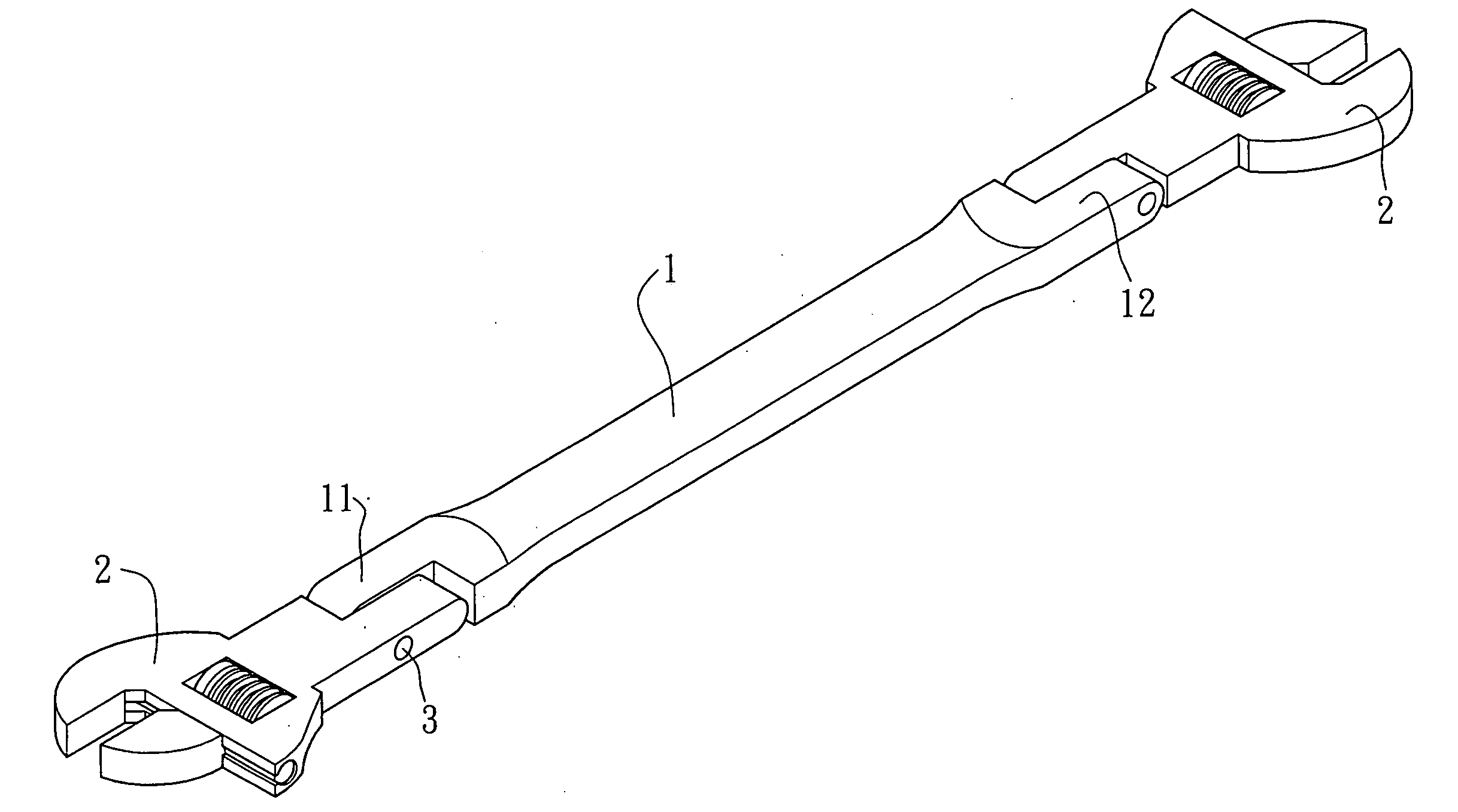
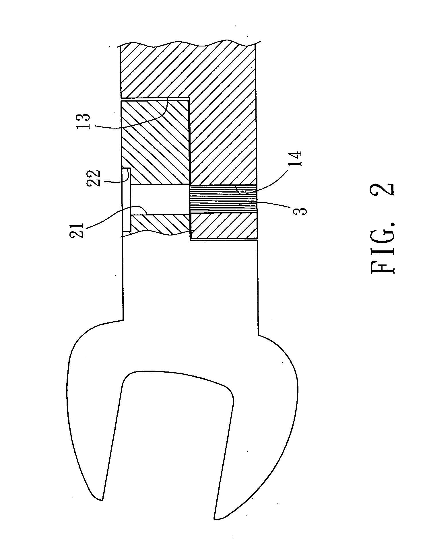
[0021] Referring to FIG. 1, a double head drive tool with each head serving as a moment of force for the other end is essentially comprised of a handle 1 of the drive tool, a first pivoting part 11 and a second pivoting part 12 are respectively provided to both ends of the handle 1. Both pivoting parts 11, 12 respectively extend a connection section 13. Each connection section 13 is connected with a work piece turning member 2. Each work piece turning member 2 is provided with a locking channel 22 and a longitudinal through hole 21. A work hole 14 is each provided on the pivoting parts 11, 12 of the handle 1. In the first preferred embodiment of the present invention, the work hole is processed to slightly indicate conic shape. Th...


PUM


Abstract

A double head drive tool with each head serving as a moment of force for the other end includes a handle having its both ends respectively provided with a pivoting part; each pivoting part being extended a connection section; each connection section being adapted with a work piece turning member; a locking channel and a longitudinal being provided to the work piece turning member; a work hole being provided on the pivoting part of the handle of the drive tool; and a locking member penetrating the work hole and the through hole to lock the work piece turning member.

Description

BACKGROUND OF THE INVENTION [0001] (a) Field of the Invention [0002] The present invention is related to a double end drive tool that each end serving the moment of force for the other end, and more particularly, to a construction of a tool having both ends respectively provided with a connection section to receive insertion of members of different types for turning work pieces to provide multiple purposes. [0003] (b) Description of the Prior Art [0004] As illustrated in FIG. 9 of the accompanying drawings, a single rock arm drive tool of the prior has provided on one side of the handle 6 of the drive tool a drive 61 to be adapted with an open-end wrench 62. A pivoting hole 63 is provided to the drive 61 to permit a locking member 64 to penetrate through it to lock the open-end wrench. The construction described above though provides the function of tightening up a nut, the middle section of the locking member 64 for being engaged in serration with the open-end wrench 62 is vulnerab...

Claims


Application Information

Patent Timeline
IPC IPC(8): B25B23/16B25B13/00B25G1/00
CPCB25B13/481B25G1/063
Inventor HSIEH, CHIH CHING
Owner HSIEH CHIH CHING
Why Eureka
Try Eureka