
Decorative cover frame assembly for selectively concealing a flat panel or high definition television display

Inactive Publication Date: 2006-07-13
ROSSI LUIS
View PDF5 Cites 34 Cited by
  • Summary
  • Abstract
  • Description
  • Claims
  • Application Information

AI Technical Summary

Benefits of technology

[0010] It is another object of the invention to produce a cover frame assembly which selectively obscures the flat panel display when the flat panel display is not activated. Accordingly, the cover frame assembly has a one-way mirror fitted within the outer frame. When the flat panel display is projecting an image, the image is eas

Problems solved by technology

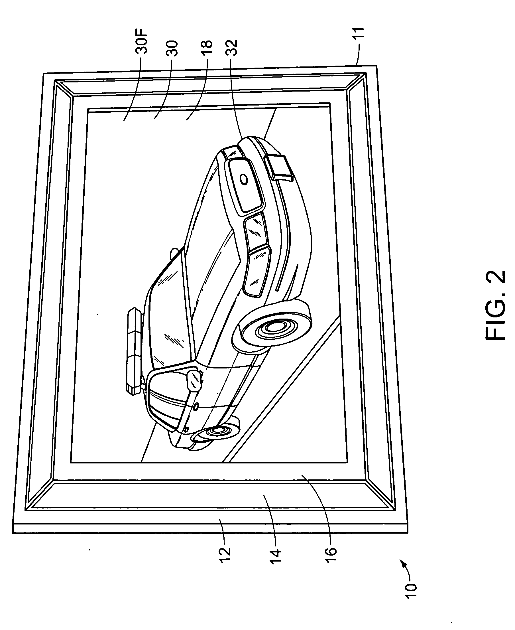
However, when the flat panel display is not being utilized to project an image, the darkened flat panel display is obscured by a reflective surface of the one-way mirror, and the combined frame and mirror assembly along with the enclosed flat panel display appear to be merely a decorative mirror.

Method used


Image

  • Decorative cover frame assembly for selectively concealing a flat panel or high definition television display
  • Decorative cover frame assembly for selectively concealing a flat panel or high definition television display
  • Decorative cover frame assembly for selectively concealing a flat panel or high definition television display

Examples


Embodiment Construction

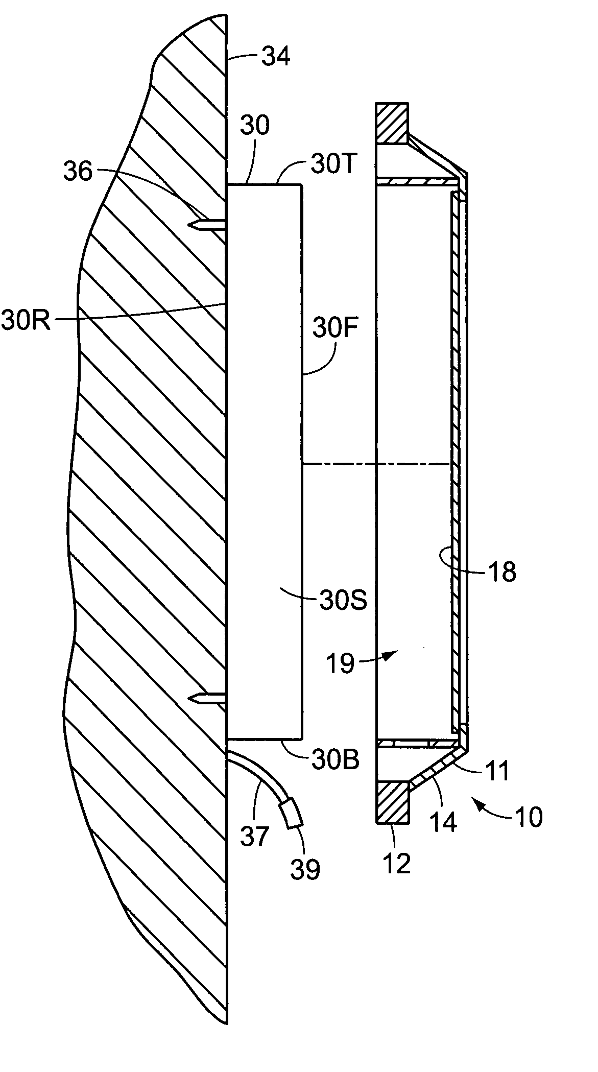
[0021]FIG. 1 illustrates a front view of a cover frame assembly 10, for use in conjunction with an existing substantially rectangular flat panel display of a high definition television or other display device. The cover frame assembly 10 is fully supported by the flat panel display and not vice versa.

[0022] The cover frame assembly 10 comprises an outer frame 11 and a substantially flat, rectangular one-way mirror 18 attached to the outer frame 11. The one-way mirror 18 has two opposing surfaces, one of which is a reflective surface. After the flat panel display has been rigidly mounted to a vertical support structure such as a wall, the cover frame assembly 10 is fitted over the flat panel display in order to substantially frame the flat panel display within the outer frame 11, and to selectively obscure the flat panel display with the reflective surface of the one-way mirror 18, as will be described. Accordingly, the frame assembly 10 is distinct from other frames in that it is n...


PUM


Abstract

A cover frame assembly for use in conjunction with an existing flat panel display of a display device such as a high definition television. The cover frame assembly comprises an outer frame, and a one-way mirror attached within the outer frame. After mounting the flat panel display to a wall, the outer frame is selectively extended over the flat panel display and is supported by the flat panel display. The images projected by the flat panel display upon activation of the display device are easily seen through the one-way mirror. When the display device is deactivated, the reflective surface of the one-way mirror obscures the flat panel display, and the combined frame assembly and flat panel display appear to be a decorative, wall mounted mirror

Description

CROSS REFERENCES AND RELATED SUBJECT MATTER [0001] This application is a continuation of patent application Ser. No. 10 / 783,803, filed in the United States Patent Office on Feb. 20, 2004.BACKGROUND OF THE INVENTION [0002] 1. Field of the Invention [0003] The invention generally relates to a cover frame assembly for mounting onto a flat panel display such as a high definition television, and in particular relates to a frame that covers a flat panel display that is mounted to a vertical surface and has a one-way mirror for selectively obscuring the flat panel display when the display is not activated. [0004] 2. Description of the Related Art [0005] Cathode ray tubes have been used for many years in a variety of display devices including television sets. More recently, flat panel displays such as plasma and LCD display panels have been developed. Various mounting frames have been devised for attaching these flat panel displays onto a vertical support structure such as a wall. As unobtr...

Claims


Application Information

Patent Timeline
IPC IPC(8): A47G1/06
CPCA47G1/02G02F1/133553G06F1/1607H04N5/64Y10S248/917
Inventor ROSSI, LUIS
Owner ROSSI LUIS
Learn More