Pre-mounting of a sensor

a sensor and pre-mounting technology, applied in the field of pre-mounting devices, to achieve the effect of convenient pre-mounting and easy adjustmen

Inactive Publication Date: 2006-07-13
DR JOHANNES HEIDENHAIN GMBH
View PDF15 Cites 7 Cited by
  • Summary
  • Abstract
  • Description
  • Claims
  • Application Information

AI Technical Summary

Benefits of technology

[0005] It is an object of the invention to provide those skilled in the art with means for pre-mounting a structural part to be mounted to the attachment surface in an adjusted position, said means allowing easy pre-mounting and, in particular, easy adjustment.

Problems solved by technology

The final mounting by an adhesive bond as mentioned in the introduction of said document stringently requires the adjusted position to be set before initiating the adhesive bonding, because corrections are not possible after the adhesive bond has been realized.

Method used


Image

  • Pre-mounting of a sensor
  • Pre-mounting of a sensor
  • Pre-mounting of a sensor

Examples


Embodiment Construction

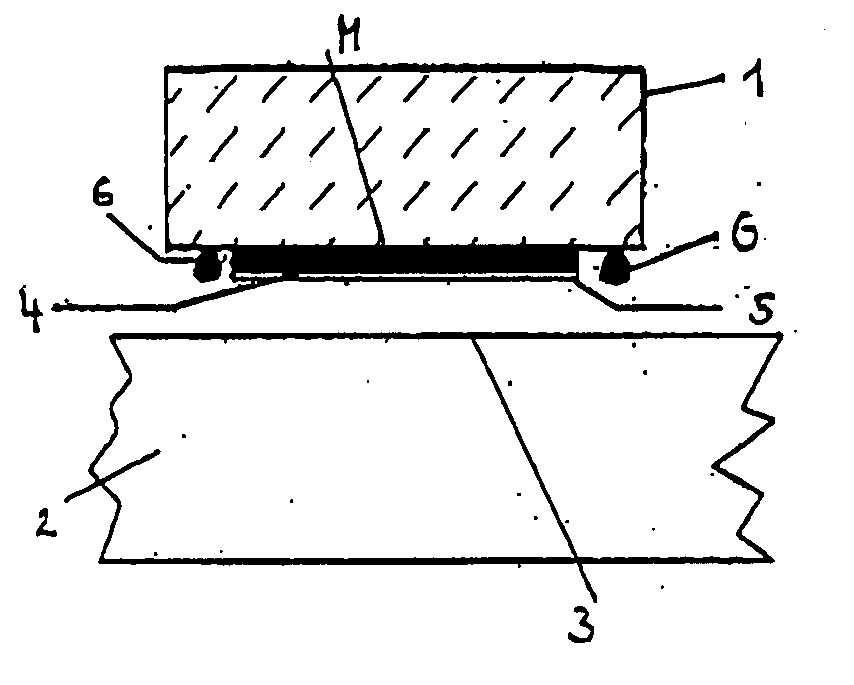
[0039]FIG. 1 shows a schematic sectional view of a sensor element 1, in a phase of the mounting process, before the sensor element 1 is mounted to a part 2. In the embodiment shown, the sensor element 1 is part of a measuring system (not shown in detail), which detects, for example, the movement of one machine part relative to another machine part. However, the sensor element may also be any other structural part which is to be mounted to an attachment surface or an attachment part in a determined position to be adjusted. It is merely essential for the following description that the element 1 be mounted to the part 2, e.g. to an attachment surface thereof, to achieve a position adjusted with high precision. The adjustment may relate to the part 2 or to a third part.

[0040] Mounting of the sensor element 1 to the part 2 is effected by connecting a mounting surface M of the sensor element 1 to the attachment surface 3, e.g. by means of an adhesive bond. For this purpose, an adhesive l...


PUM


Abstract

What is described is a pre-mounting system for pre-mounting a structural part to an attachment surface, wherein at least two heads, respectively provided as eccentrics, are provided at the attachment surface, the structural part comprises at least one recess and can be hung up on the attachment surface by said heads engaging said recess/recesses.

Description

FIELD OF THE INVENTION [0001] The invention relates to a pre-mounting device for a structural part which is mountable in an adjusted position to an attachment surface. The invention further relates to a structural part which is pre-mounted by means of said pre-mounting element. Further, the invention relates to a pre-mounting system for pre-mounting a structural part to an attachment surface, as well as to a method of mounting a structural part to an attachment surface. BACKGROUND OF THE INVENTION [0002] In many cases, structural parts have to be mounted to attachment surfaces in predetermined positions. The predetermined position is usually set in an adjusting step and the structural part is then finally mounted to the attachment surface. The adjusted position should, of course, remain unchanged as far as possible. This problem is exemplified, for example, in length or angle measuring systems, in which a transducer element to be optically sensed has to be mounted to the correspondi...

Claims


Application Information

Patent Timeline
Patent Type & Authority Applications(United States)
IPC IPC(8): A47H1/10E21B47/022
CPCF16B5/0225F16B11/006G01D11/30
Inventor BOGE, LUDWIGFRANZ, HEINZ-GUNTHERFREITAG, HANS-JOACHIMSCHMIDT, ANDREAS
Owner DR JOHANNES HEIDENHAIN GMBH
Why Eureka
Try Eureka