
Method and apparatus for evaluating a proposed solution to a constraint problem

Inactive Publication Date: 2006-07-06
GLOBAL NUCLEAR FUEL -- AMERICAS
View PDF6 Cites 15 Cited by
  • Summary
  • Abstract
  • Description
  • Claims
  • Application Information

AI Technical Summary

Benefits of technology

[0009] The configured objective function may then usable as part of an optimization process, or may be usable as a tool when a user assesses a candidate solution to an optimization problem. Because of the flexibility of the invention, changes in optimality conditions, constraint term definitions, and weight factors are readily accommodated.

Problems solved by technology

Most problems encountered in engineering design are nonlinear by nature and involve the determination of system parameters that satisfy certain goals for the problem being solved.

Method used


Image

  • Method and apparatus for evaluating a proposed solution to a constraint problem
  • Method and apparatus for evaluating a proposed solution to a constraint problem
  • Method and apparatus for evaluating a proposed solution to a constraint problem

Examples


Embodiment Construction

The Generic Objective Function

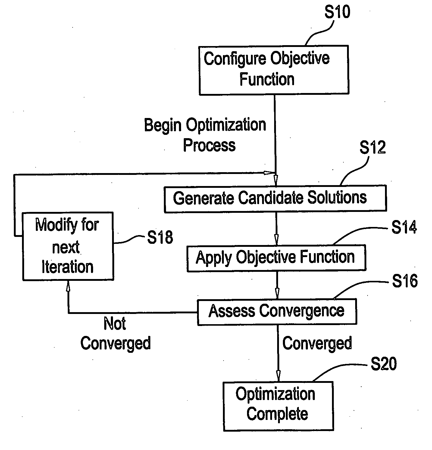
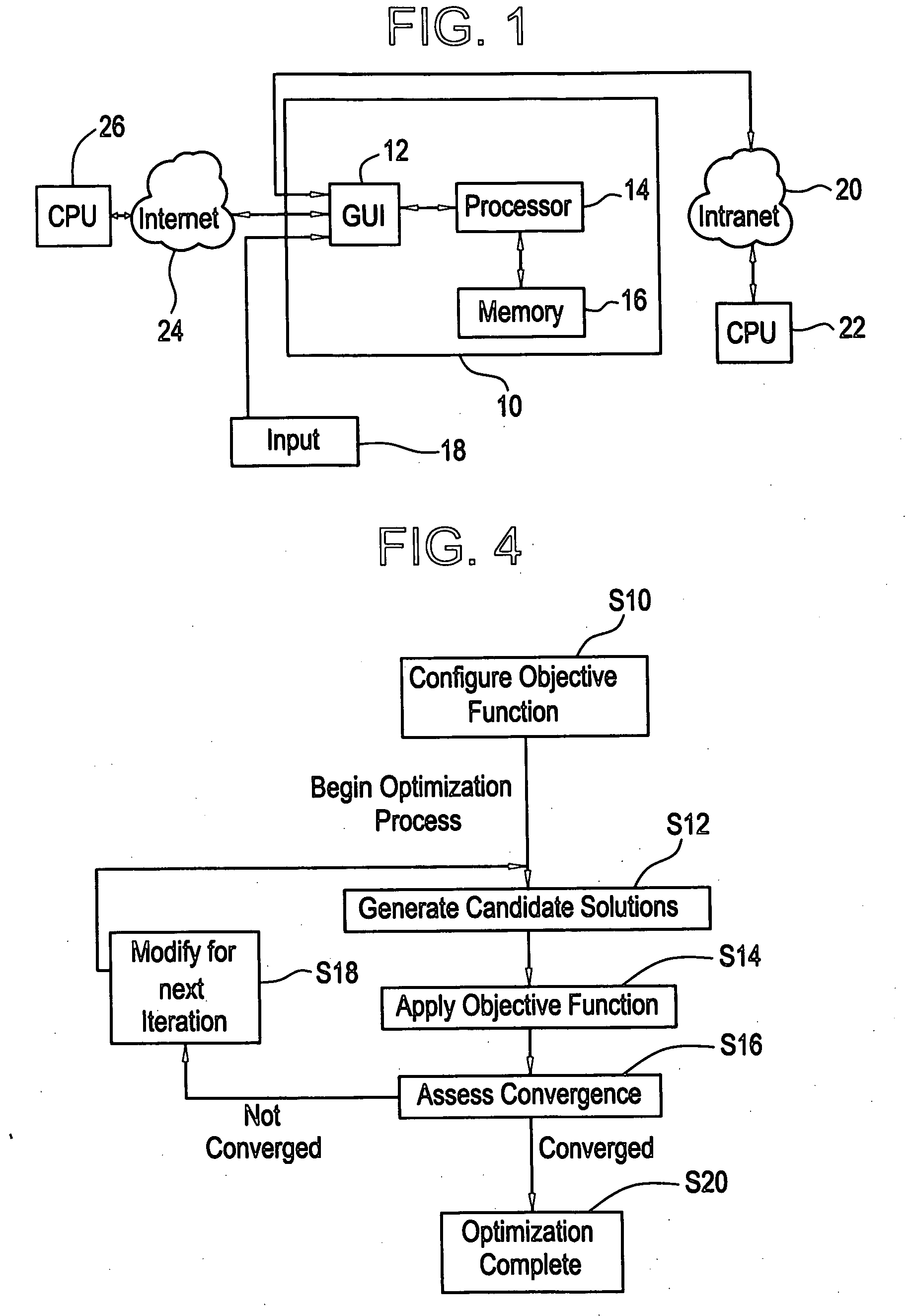
[0015] The present invention provides a generic definition of an objective function, which is applicable across a wide variety of constraint and optimization problems. Namely, the generic objective function is applicable to any large scale, combinatorial optimization problem in discrete or continuous space such as boiling water reactor core design, pressurized water reactor core design, transportation scheduling, resource allocation, etc. The generic objective function is defined as a sum of credit and penalty components. A penalty component includes a penalty term multiplied by an associated penalty weight. A credit component includes a credit term multiplied by an associated credit weight. The credit terms represent the optimality conditions for the problem. The penalty terms represent the constraints for the problem. Each credit term is a mathematical expression that quantifies an optimality condition. Each penalty term is a mathematical expression ...


PUM


Abstract

A method of evaluating constraint functions, the evaluation being based at least in part on a control blade movement criteria.

Description

BACKGROUND OF THE INVENTION [0001] Most problems encountered in engineering design are nonlinear by nature and involve the determination of system parameters that satisfy certain goals for the problem being solved. Such problems can be cast in the form of a mathematical optimization problem where a solution is desired that minimizes a system function or parameter subject to limitations or constraints on the system. Both the system function and constraints are comprised of system inputs (control variables) and system outputs, which may be either discrete or continuous. Furthermore, constraints may be equalities or inequalities. The solution to a given optimization problem has either or both of the following characteristics: 1) minimizes or maximizes a desired condition or conditions, thus satisfying the optimality condition and 2) satisfies the set of constraint equations imposed on the system. [0002] With the above definitions, several categories of optimization problems may be defi...

Claims


Application Information

Patent Timeline
IPC IPC(8): G06F9/46
CPCG06N99/005G05B13/0265G06N20/00
Inventor ASGARI, MEHDIKROPACZEK, DAVID JOSEPHKVAALL, GERALD DEAN JR.JACKSON, ROLAND OTTOSUTTON, STEVEN BARRYOYARZUN, CHRISTIAN CARLOS
Owner GLOBAL NUCLEAR FUEL -- AMERICAS
Learn More