Eureka AIR delivers breakthrough ideas for toughest innovation challenges, trusted by R&D personnel around the world.

Room mode bass absorption through combined diaphragmatic & helmholtz resonance techniques

a diaphragmatic helmholtz resonance and combined technology, applied in the field of acoustics, can solve the problems of inability to place acoustical treatment, resistive absorption is not an effective standing wave absorption method, and the material depth and area is not large enough to achieve the effect of reducing peak and dip frequency response errors, improving absorption and total room mode attenuation

Inactive Publication Date: 2006-07-06
PERFORMANCE MEDIA IND
View PDF4 Cites 3 Cited by
  • Summary
  • Abstract
  • Description
  • Claims
  • Application Information

AI Technical Summary

Benefits of technology

[0019] The present invention provides an acoustical bass absorber which reduces peak and dip frequency response errors caused by interference from naturally occurring axial standing waves in rectangular rooms. The apparatus uses two forms of simple harmonic resonance: pistonic diaphragm resonance and Helmholtz cavity resonance. The pistonic diaphragm resonance is achieved by attaching a rigid planar membrane to metal springs. The Helmholtz cavity resonance is achieved by constructing an enclosed chamber attached to an open cylindrical tube. Coupling these two dissipation devices leads to several-fold improvement in absorption and total room mode attenuation.
[0020] The inventive apparatus uses the resonance character of the pistonic diaphragm to increase the magnitude of absorption of a coupled Helmholtz chamber. The damping character of the springs is minimal compared to the sound absorption from the frictional loss in the Helmholtz cavity.
[0021] It is therefore an object or feature of the present invention to provide a new and improved method and apparatus to reduce frequency response errors in small room acoustics.
[0022] It is another object of the present invention to provide an apparatus to improve the effectiveness of room mode absorption by achieving more accurate tuning of the absorption device to the target resonant frequency in the room.
[0023] It is another object of the present invention to provide an increase in the magnitude of absorption in a relatively small surface area of treatment.
[0024] It is a still further object of the present invention to provide a method and apparatus for controlling room modes to achieve accurate frequency response and consistent sound quality at all listener locations.

Problems solved by technology

One challenge of small room acoustics is reducing frequency response errors introduced by standing waves, also known as “room modes”.
Deficiencies of resistive absorption are its broad frequency range of absorption (narrow band absorption is preferable for treating room modes, so non-modal frequencies are unaffected), and that it requires significant depth and area of material in the room to be effective at the low frequencies typical of room modes.
Because room boundaries are the most common locations for acoustical treatments, resistive absorption is not an effective method of standing wave absorption.
It is generally not practical to place acoustical treatments more than a few inches inward in the room from the room's boundary—low frequencies typical of room modes would potentially require treatments to be suspended one to three feet inward from the room's boundary.
The diaphragm's tympanic flexing dissipates sound energy as heat and causes damping of the resonance.
Although constructing accurately tuned diaphragm absorbers is difficult, it is possible to achieve a narrow frequency range of absorption (avoiding attenuation of adjacent non-modal frequencies).
One deficiency of tympanic and pistonic diaphragm absorbers is that they can reradiate the sound energy of the standing wave into the room at a later time.
The delayed reradiation of the sound energy is pyschoacoustically undesirable in a listening environment.
Similar to echoes in a reverberant space, delayed radiation of bass energy in a modal environment seriously distracts from the desired effect of the program material (see Everest, supra).
A challenge with Helmholtz absorbers is that the chamber must be very large to achieve low frequency resonance (in the region of frequency relevant to small room acoustics).
Another limitation is the absorption coefficient produced by the resonance is considered to be applicable only over the tube opening area; numerous absorbers may be required to attenuate room modes (see Everest, supra).
It was determined after construction however that too much attenuation had been achieved and some of the cavities were later filled.
Active cancellation would inject a signal into the room at equal amplitude and opposite polarity as the standing wave, resulting in cancellation.
Active cancellation appears much more complicated than passive mechanical solutions.

Method used


Image

  • Room mode bass absorption through combined diaphragmatic & helmholtz resonance techniques
  • Room mode bass absorption through combined diaphragmatic & helmholtz resonance techniques
  • Room mode bass absorption through combined diaphragmatic & helmholtz resonance techniques

Examples


Embodiment Construction

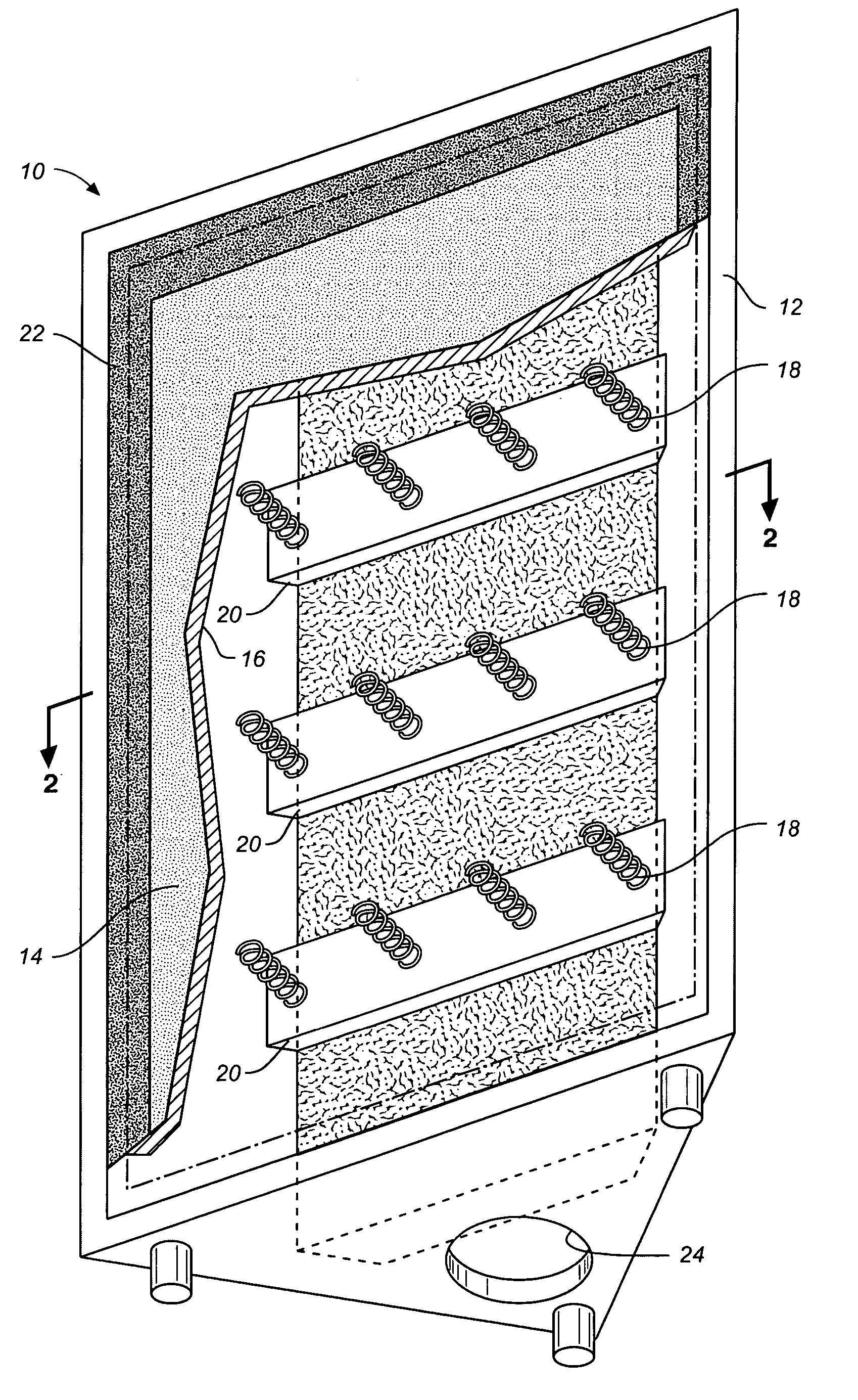
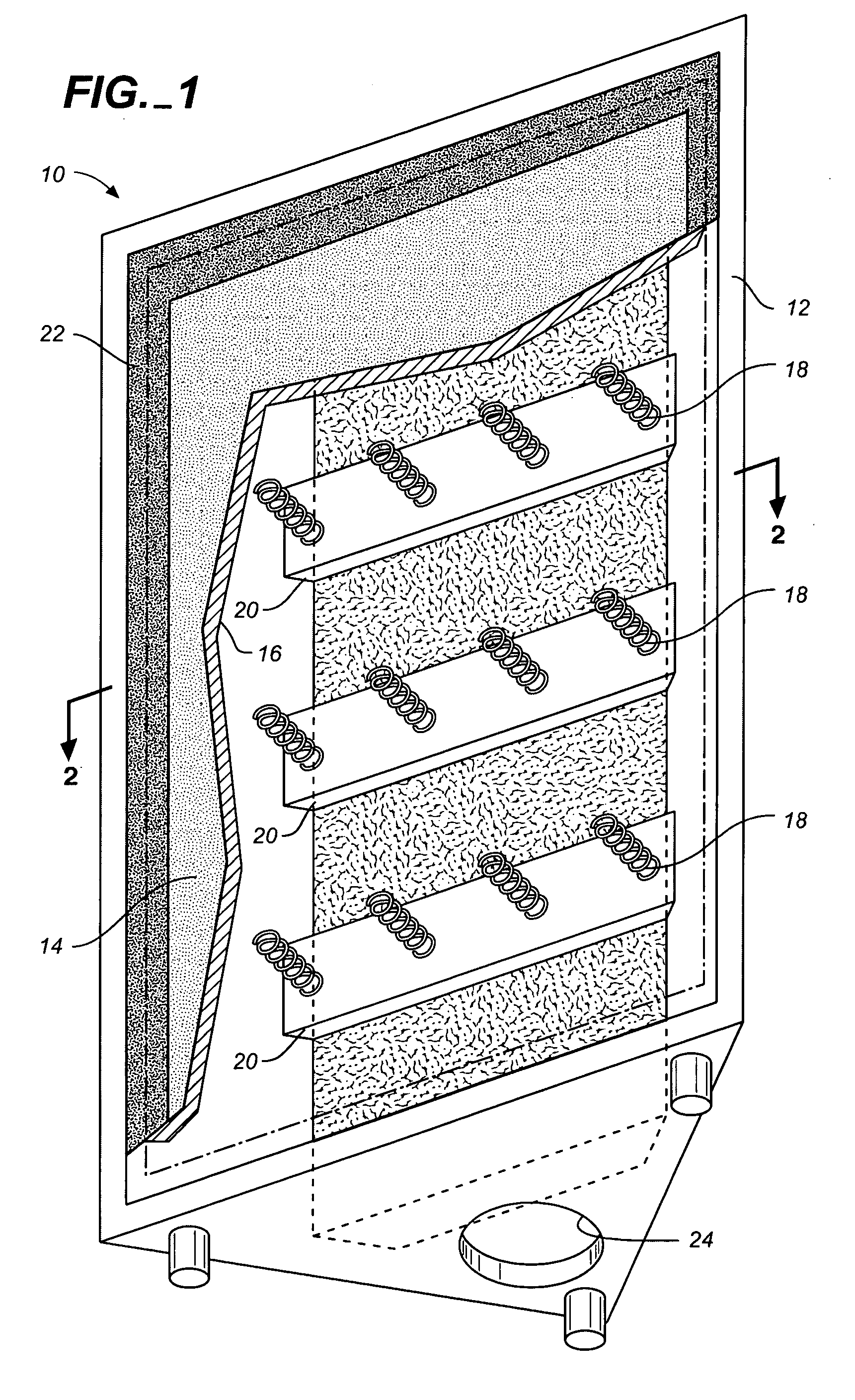
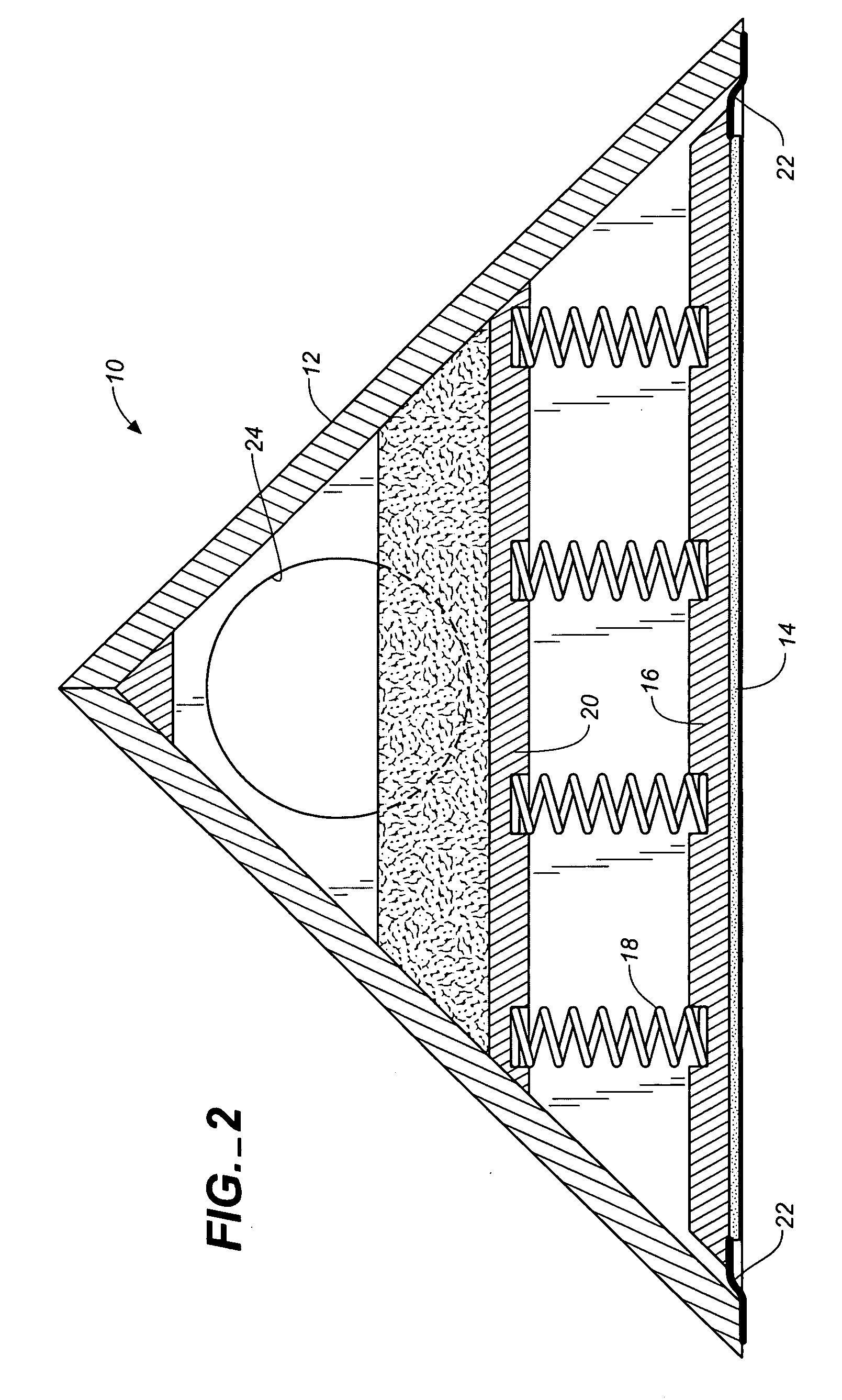
[0032] Referring to FIGS. 1 through 2, wherein like reference numerals refer to like components in the various views, FIG. 1 is a front perspective view of an acoustical bass absorber apparatus 10 of this invention; and FIG. 2 is a cross-sectional view thereof. Apparatus 10 includes a cabinet or housing portion 12 defining an internal volume. The housing 12 includes a pistonic diaphragm resonance 14 including a front plate or rigid planar member 16 attached to one or a plurality of metal springs 18. One or more cross supports 20 secure the other end of the spring(s) 18 within the housing. Rubber gasket 22 forms an airtight seal around the entire perimeter of the front plate / housing interface. A Helmholtz resonance port hole and tube 24 is contained in the housing 14 and coupled to the pistonic diaphragm resonance 14.

[0033] One embodiment of the inventive apparatus was motivated by the need for a custom bass absorber to attenuate room modes in a home theater installation. In this pa...


PUM


Abstract

An acoustical bass absorber which reduces peak and dip frequency response errors caused by interference from naturally occurring axial standing waves in rectangular rooms. The apparatus uses two forms of simple harmonic resonance: pistonic diaphragm resonance and Helmholtz cavity resonance. The pistonic diaphragm resonance is achieved by attaching a rigid planar membrane to metal springs. The Helmholtz cavity resonance is achieved by constructing an enclosed chamber attached to an open cylindrical tube. Coupling these two dissipation devices leads to several-fold improvement in absorption and total room mode attenuation.

Description

BACKGROUND OF THE INVENTION [0001] 1. Technical Field [0002] The present invention relates generally to acoustics, and more particularly to an improved method and apparatus to reduce frequency response errors in small room acoustics. [0003] 2. Background Art [0004] One challenge of small room acoustics is reducing frequency response errors introduced by standing waves, also known as “room modes”. There are many references on room modes in the literature, see, for example, P. M. Morse, Vibration and Sound, (McGraw Hill, N.Y. 1948), p. 313, 418; P. M. Morse and K. U. Ingard, Theoretical Acoustics, (McGraw Hill, N.Y., 1968), p. 576-598; J. Borwick (ed.), Loudspeaker and Headphone Handbook, (McGraw Hill, N.Y., 1968), ch. 7; and T. Welti, “How Many Subwoofers Are Enough”, presented at the AES112th Convention, Munich, Germany, 2002 May 10-13. Usually narrow in bandwidth, these frequency response errors can be up to 40 decibels in magnitude and are spatially variable within the listening e...

Claims


Application Information

Patent Timeline
Patent Type & Authority Applications(United States)
IPC IPC(8): H04R1/02H04R1/20G10K11/172
CPCG10K11/172H04R1/2873
Inventor GRIMANI, ANTHONYREILEY, EVAN
Owner PERFORMANCE MEDIA IND
Why Eureka
Eureka Blog
Learn More