
LCD device having adjustable viewing angles

a technology of adjustable viewing angle and lcd, which is applied in the field of lcd device having adjustable viewing angle, can solve the problems of increased lcd size, increased manufacturing and operation difficulty of lcd, and extra liquid crystal layer, so as to simplify the lcd structure, reduce manufacturing costs, and facilitate the choice

Inactive Publication Date: 2006-07-06
AU OPTRONICS CORP
View PDF15 Cites 63 Cited by
  • Summary
  • Abstract
  • Description
  • Claims
  • Application Information

AI Technical Summary

Benefits of technology

[0011] It is an advantage of the present invention that the first common electrode and the second common electrode can be switched to conveniently choose the narrow viewing angle mode or the wide viewing angle mode. In comparison with the prior art LCD having two liquid crystal layers, the LCD device of the present invention particularly provides the advantages of simplifying the LCD structure and reducing the manufacturing costs to facilitate the development and the application of the LCD device.
[0012] These and other objects of the claimed invention will be apparent to those of ordinary skill in the art with reference to the following detailed description of the preferred embodiments illustrated in the various drawings.

Problems solved by technology

With an increase in the LCD sizes, limitations in viewing angles of conventional twisted nematic (TN) type LCDs have been observed.
Although the viewing angle expanding technology is essential to increase a contrast of LCD, the viewing angles are limited in some LCD applications so as to allow the user to see the image only at specific angles.
Although the above-mentioned LCD allows the user to adjust the passing rate of light according to his desire for viewing angles, the use of the extra liquid crystal layer increases the difficulty in manufacturing and operating the LCD.
Therefore, how to reduce the complexity in the structure of LCD and provide a convenient method to adjust the viewing angles of LCD are important issues.

Method used


Image

  • LCD device having adjustable viewing angles
  • LCD device having adjustable viewing angles
  • LCD device having adjustable viewing angles

Examples


Embodiment Construction

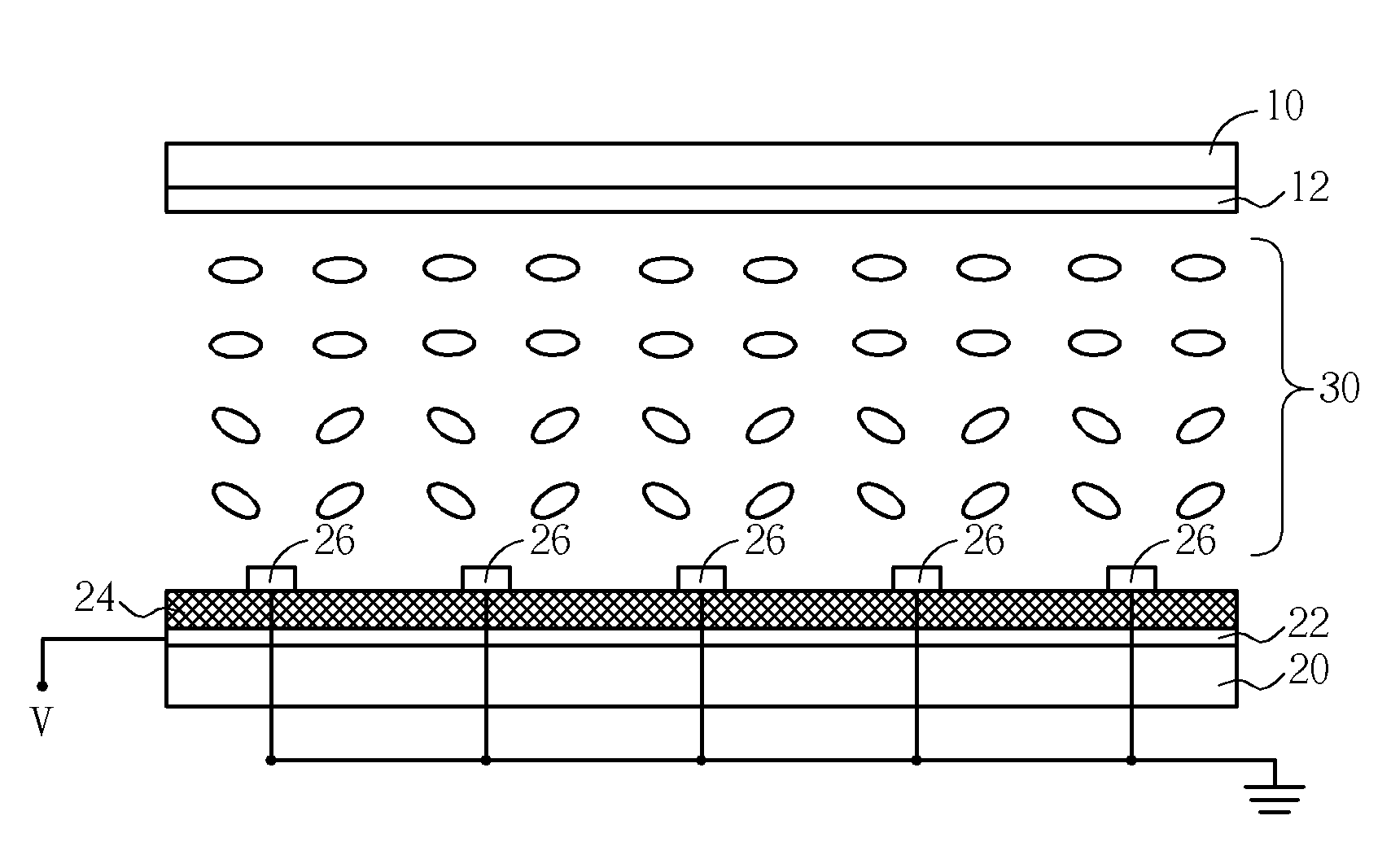
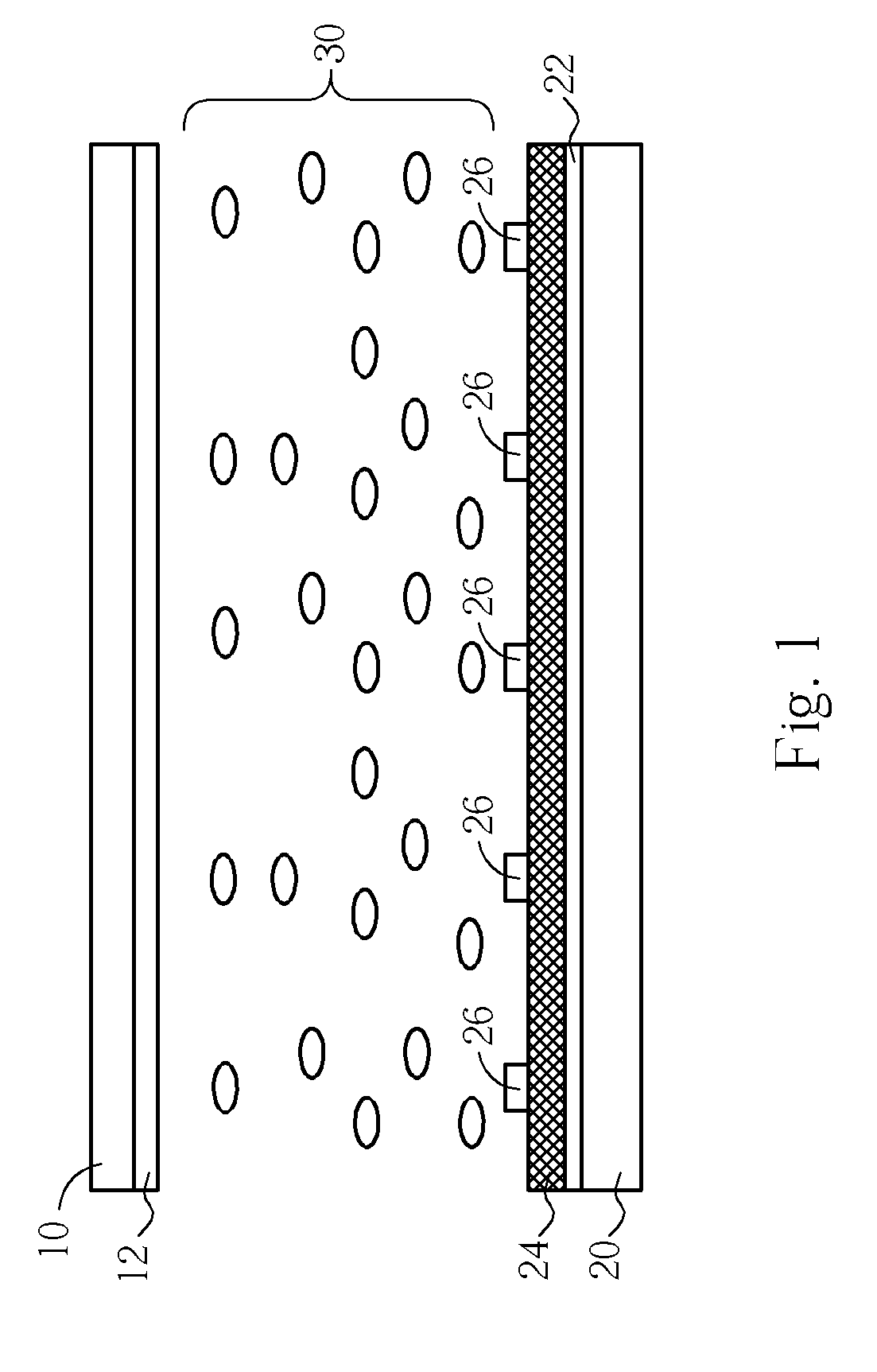
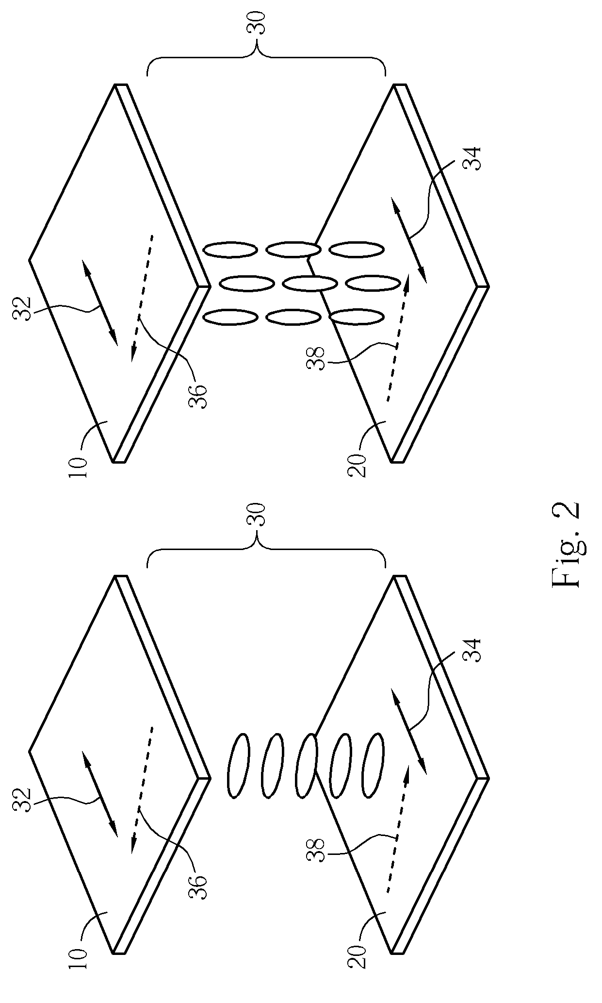
[0019] Referring to FIG. 1, FIG. 1 is a cross-sectional diagram of an LCD device having adjustable viewing angles according to the present invention. As shown in FIG. 1, an LCD device has two parallel substrates 10 and 20, and a liquid crystal layer 30 is filled in a gap between the substrate 10 and the substrate 20. In a preferred embodiment of the present invention, the substrate 10 is a color filter substrate with a plurality of red, green, and blue color filters, and a black matrix (not shown in FIG. 1) is also formed on the substrate 10. Light penetrates through the substrate 10 to produce the three primary colors of red, green, and blue to compose colorful images. The substrate 20 is a thin-film transistor substrate with TFT array, capacitors, scan lines and signal lines. The substrate 20 is used to drive pixel electrodes and rotation of liquid crystal. In other embodiments of the present invention, the substrate 20 can be a color-filter-on-array (COA) substrate or an array-on...


PUM


Abstract

An LCD device having adjustable viewing angles includes a first substrate, a second substrate, and a liquid crystal layer disposed between the first substrate and the second substrate. The first substrate has a first common electrode. The second substrate has a pixel electrode, a second common electrode, and an insulating layer formed between the pixel electrode and the second common electrode. While in a narrow viewing angle mode of the LCD device, a driving voltage is applied to the pixel electrode, the first common electrode is grounded, and the second common electrode is floating. While in a wide viewing angle mode of the LCD device, a driving voltage is applied to the pixel electrode, the second common electrode is grounded, and the first common electrode is floating.

Description

BACKGROUND OF INVENTION [0001] 1. Field of the Invention [0002] The present invention relates to an LCD device having adjustable viewing angles, and more particularly, to an LCD device capable of switching a wide viewing angle mode to a narrow viewing angle mode or switching a narrow viewing mode to a wide viewing angle mode. [0003] 2. Description of the Prior Art [0004] With an increase in the LCD sizes, limitations in viewing angles of conventional twisted nematic (TN) type LCDs have been observed. To remove the limitations in the viewing angles and allow the users to observe undistorted images at various viewing angles, viewing angle expanding technology has been researched. For example, the use of a viewing angle compensation film, forming different pre-tilt angle directions in a pixel region, or in-plane switching (IPS) type LCDs are proposed to expand the viewing angles of LCDs. [0005] Although the viewing angle expanding technology is essential to increase a contrast of LCD, ...

Claims


Application Information

Patent Timeline
IPC IPC(8): G02F1/1343
CPCG02F1/1323G02F1/1343G02F2001/134318G02F1/134318
Inventor WU, MING-CHOULIN, YUNG-LUNTSAI, MENG-CHANGCHEN, PO-LUN
Owner AU OPTRONICS CORP
Learn More