
Method and device for pressure control of electric injection molding machine

a technology of electric injection molding machine and pressure control, which is applied in the direction of auxillary shaping apparatus, manufacturing tools, ceramic shaping apparatus, etc., can solve the problems of difficult to completely eliminate such control failure, difficult to precisely control melt pressure, and poor control of propelling power

Inactive Publication Date: 2006-07-06
UBE MASCH CORP LTD
View PDF9 Cites 23 Cited by
  • Summary
  • Abstract
  • Description
  • Claims
  • Application Information

AI Technical Summary

Benefits of technology

The present invention provides a method for controlling pressure in an electric injection molding machine by detecting the angular velocity of the motor that propels the screw and estimating the melt pressure value based on the detected angular velocity and a torque command value. The observer, which is a differential equation, is used to obtain the estimated melt pressure value. The higher resistance against noises is achieved because the equation for calculating the estimated melt pressure value contains no differential term. The technical effect of the invention is to control the melt pressure precisely without the use of any pressure sensor such as a load cell.

Problems solved by technology

In this case, the propelling power may not be controlled well as a phenomenon.
Nevertheless, it is extremely difficult to completely eliminate such the control failure.
Therefore, depending on adjusters, adjusted conditions may differ subtly and result in individually different controlled conditions as a problem.
As a result, a precise melt pressure control is made difficult as a problem.

Method used


Image

  • Method and device for pressure control of electric injection molding machine
  • Method and device for pressure control of electric injection molding machine
  • Method and device for pressure control of electric injection molding machine

Examples


Embodiment Construction

[0040] The embodiments of the present invention will now be described based on the drawings.

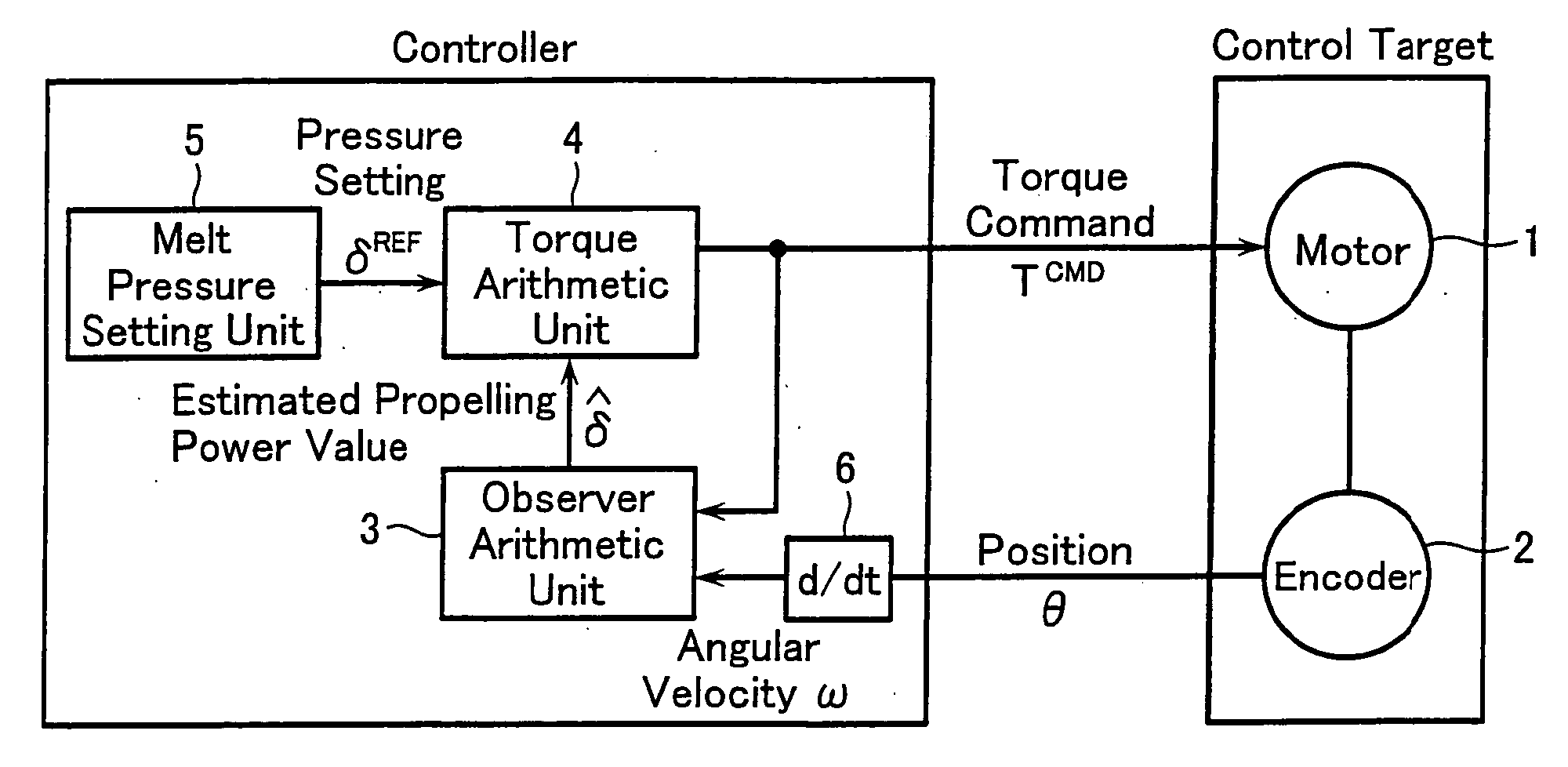
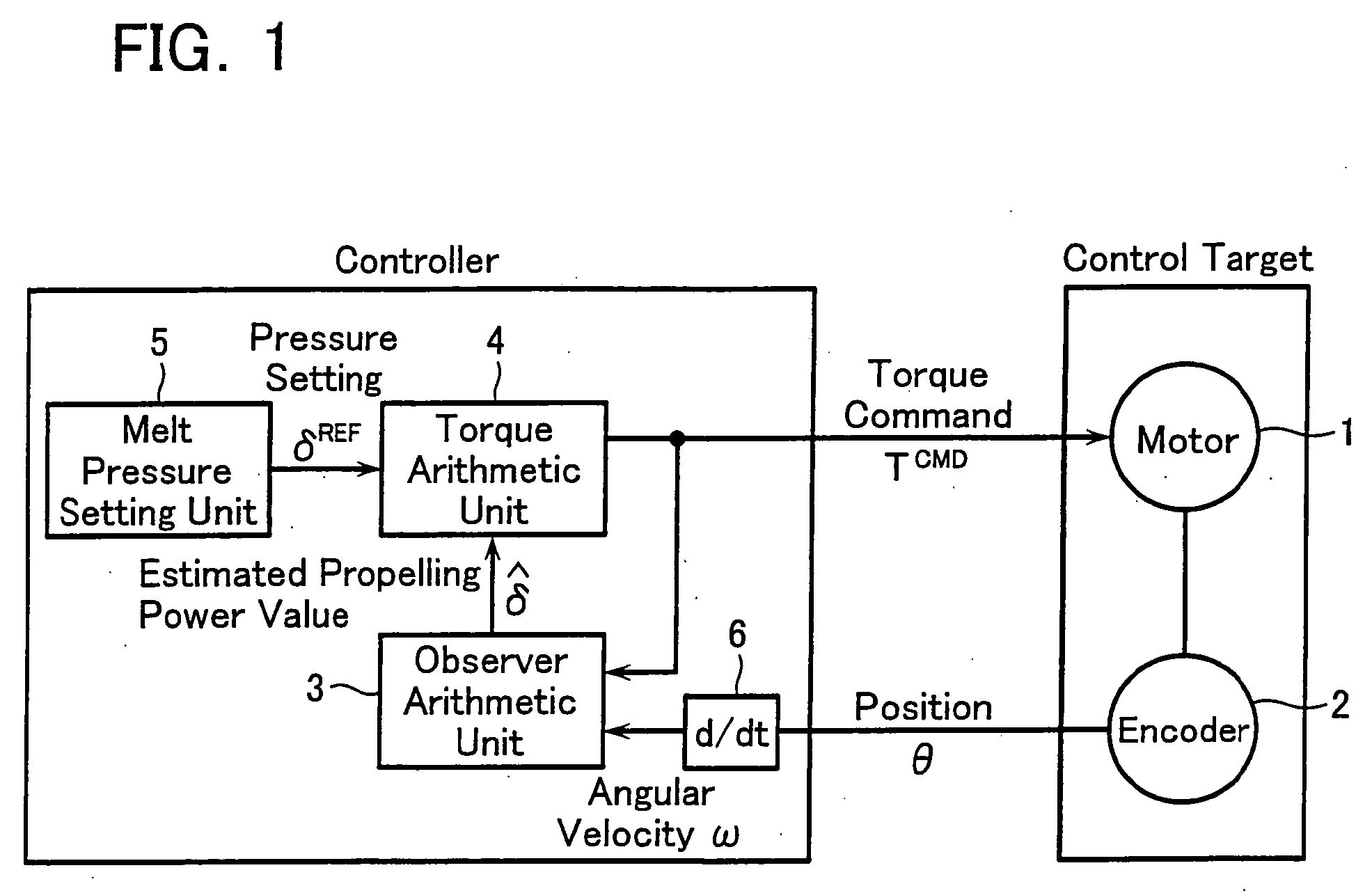
[0041]FIG. 1 is a block diagram showing a configuration of a pressure controller for an electric injection molding machine according to an embodiment of the present invention.

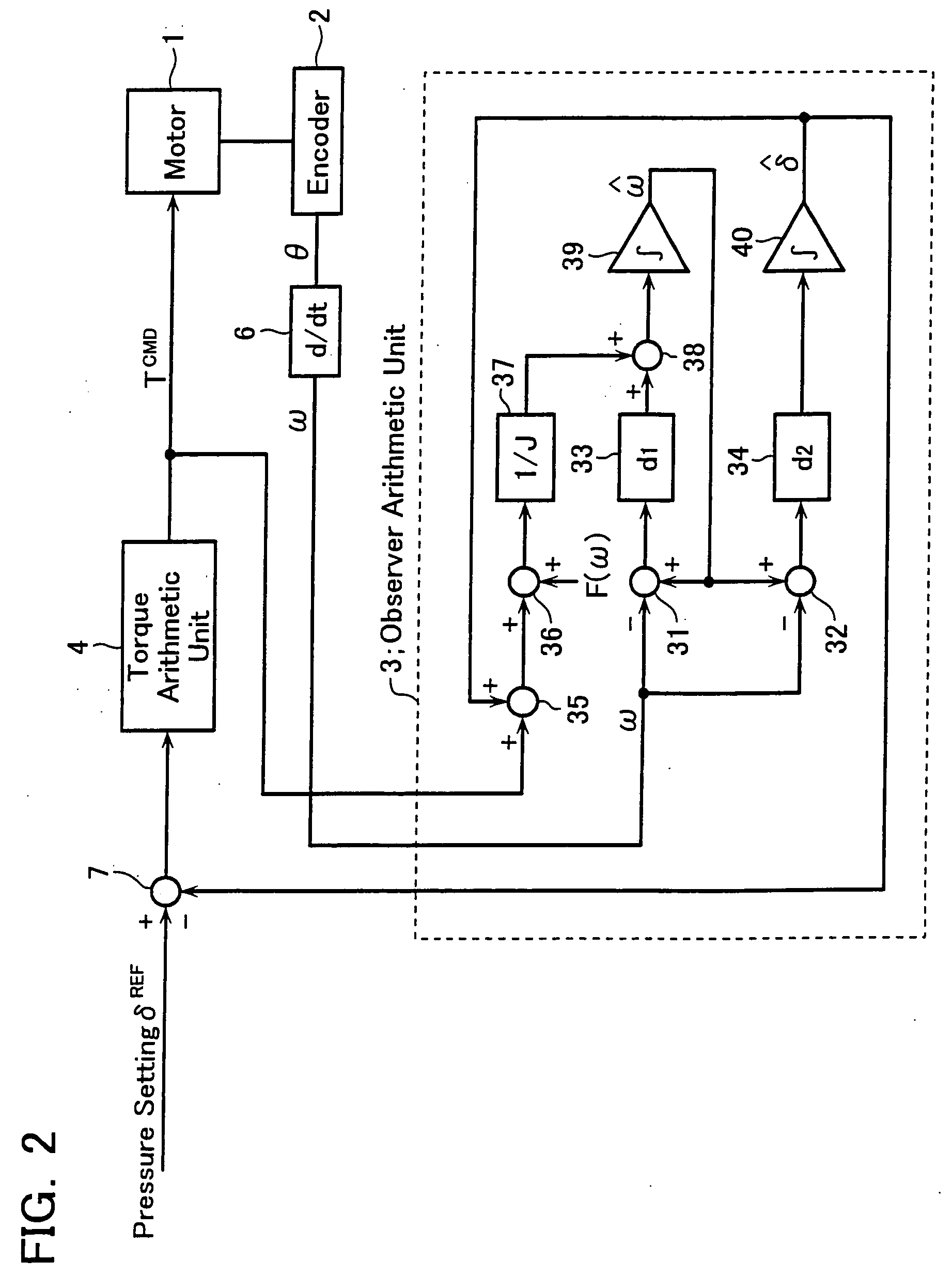
[0042] A control target or motor 1 is an injection motor operative to move a screw back and forth in an injection cylinder, not shown. The motor 1 is equipped with an encoder 2, which detects positional information (rotational angle) θ of the motor and provides it to external. The positional information θ from the encoder 2 is converted at a differentiator 6 into an angular velocity ω, which is then fed to an observer arithmetic unit 3. The observer arithmetic unit 3 estimates the propelling power of the screw (melt pressure) δ based on the output ω from the differentiator 6. Based on a melt pressure setting δREF set at a melt pressure setting unit 5 and an estimated melt pressure value δˆ derived at the observer arith...


PUM

PropertyMeasurementUnit
pressureaaaaaaaaaa
angular velocityaaaaaaaaaa
melt pressureaaaaaaaaaa

Abstract

A rotational angle of a motor operative to propel forward a screw in an injection molding machine is detected at an encoder. An output from the encoder is employed to obtain an angular velocity ω of the motor. From the obtained angular velocity ω, an estimated melt pressure value δˆ that contains no differential term is derived using a certain observer theory. The estimated melt pressure value δˆ is employed to calculate a torque command value TCMD for the motor, which is fed back to the motor. Thus, precise propelling power control unaffected by noises can be executed without the use of a pressure sensor such as a load cell.

Description

TECHNICAL FIELD [0001] The present invention relates to a method and apparatus for controlling pressure in an electric injection molding machine. BACKGROUND ART [0002] A typical electric molding machine employed in the art senses pressure using a pressure sensor in a control target (such as mold open / close, extrusion, and nozzle touch) and, based on a signal from the pressure sensor, configures a closed-loop control circuit to control the propelling power. [0003] Specifically, for control of injection pressure, a load cell is arranged at the root of a screw, for example, to sense a force that pushes the screw (a forward force) in the form of pressure by the load cell. Then, based on the sensed pressure, feedback control is applied such that the pressure to be sensed at the load cell reaches a desired pressure value, thereby controlling the propelling power of the screw. [0004] A measured signal output from a general pressure sensor such as the load cell is a weak analog signal. An e...

Claims


Application Information

Patent Timeline
Patent Type & Authority Applications(United States)
IPC IPC(8): B29C45/76B29C45/77B29C48/76B29C48/92
CPCB29C45/77B29C2945/76006B29C2945/76013B29C2945/7602B29C2945/7612B29C47/92B29C2945/76498B29C2945/76605B29C2945/76665B29C2945/76859B29C2945/7621
Inventor OKAZAKI, YOSHINORI
Owner UBE MASCH CORP LTD
Learn More