
Secure firmware update

a firmware update and security technology, applied in the field of secure firmware update, can solve the problems of user frustration, inability to protect from malicious or other unwanted attacks, and the boot process takes a relatively long period of time, and achieve the effect of improving the efficiency of firmware upda

Inactive Publication Date: 2006-06-29
KINGLITE HLDG INC
View PDF11 Cites 245 Cited by
  • Summary
  • Abstract
  • Description
  • Claims
  • Application Information

AI Technical Summary

Benefits of technology

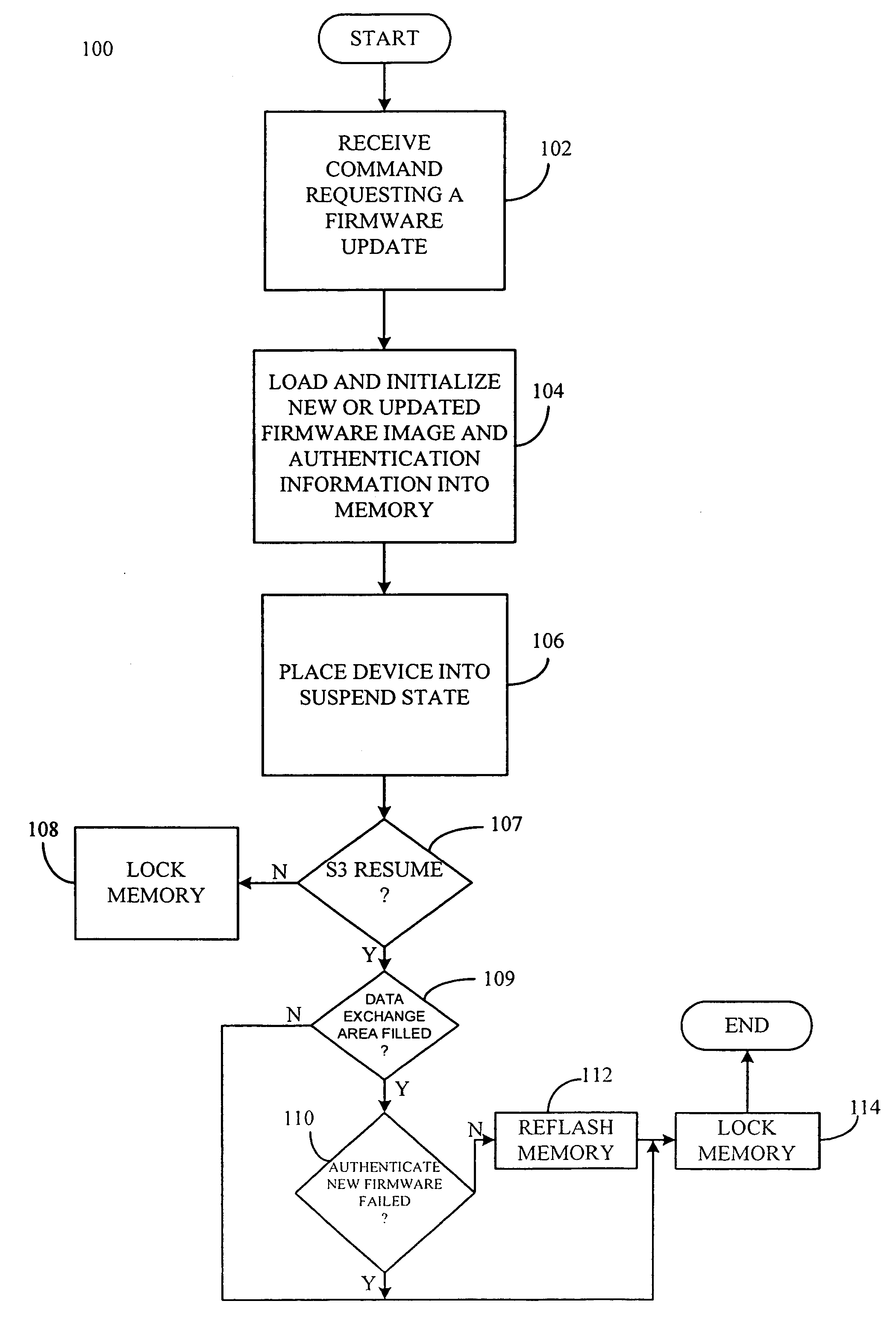
[0008] The S3 resume mode refers to a change in device power management state, for example, from the S3 state to the S0 state. The S3 state, referred to as standby, is an intermediate power saving state in which some of the components of the device, for example, the central processing unit power down to save energy. The S0 state refers to the normal full power state of the device. When the device is in the S3 state, the contents of the system memory are preserved in order to allow the device to quickly enter the S0 state. By implementing the flash or memory update during the S3 state, the security and authentication of the update is assured, along with avoiding the latency that accompanies conventional cold boot processes.
[0010] An advantage provided by the present invention is that device security is maintained as the firmware is only replaced or updated when both the update firmware image and the source of the update firmware image are from authorized or trusted sources.
[0011] Another advantage provided by the present invention is that firmware updating efficiency is improved as a cold boot process does not have to be performed.

Problems solved by technology

Because the flash memory is updateable, it is also vulnerable to malicious or other unwanted attack.
Such firmware would essentially be immune from detection by existing virus detection programs due to the unsecure nature of the flash update process.
A drawback associated with using the cold boot process to control the locking of the applicable memory is that the cold boot process takes a relatively long period of time (e.g. upwards of three minutes) to complete; thereby, causing user frustration.

Method used


Image

  • Secure firmware update
  • Secure firmware update
  • Secure firmware update

Examples


Embodiment Construction

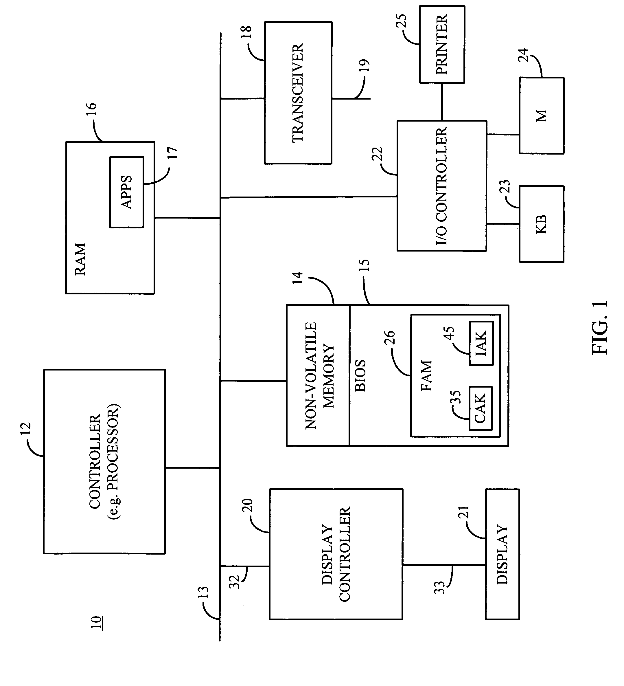
[0016]FIG. 1 is a schematic block diagram of an exemplary electronic device 10, for example, a desk top computer, a laptop computer, tablet PC, personal digital assistant (PDA), Internet appliance; embedded device, for example, routers and set top boxes, wireless communication devices, for example, cellular telephones or other suitable devices and combinations thereof incorporating the secure firmware update functionality according to the present invention. For purposes of illustration and not limitation, the electronic device 10 is represented as a laptop computer including at least one processor or other suitable controller 12, a first memory 14 (e.g. NVRAM, ROM, flash memory or other suitable non-volatile memory), a second memory 16 (e.g. RAM or other suitable volatile memory), a transceiver 18, a display controller 20 and an input / output (I / O) controller 22. The first memory 14, second memory 16, transceiver 18, display controller 20 and I / O controller 22 are all interconnected ...


PUM


Abstract

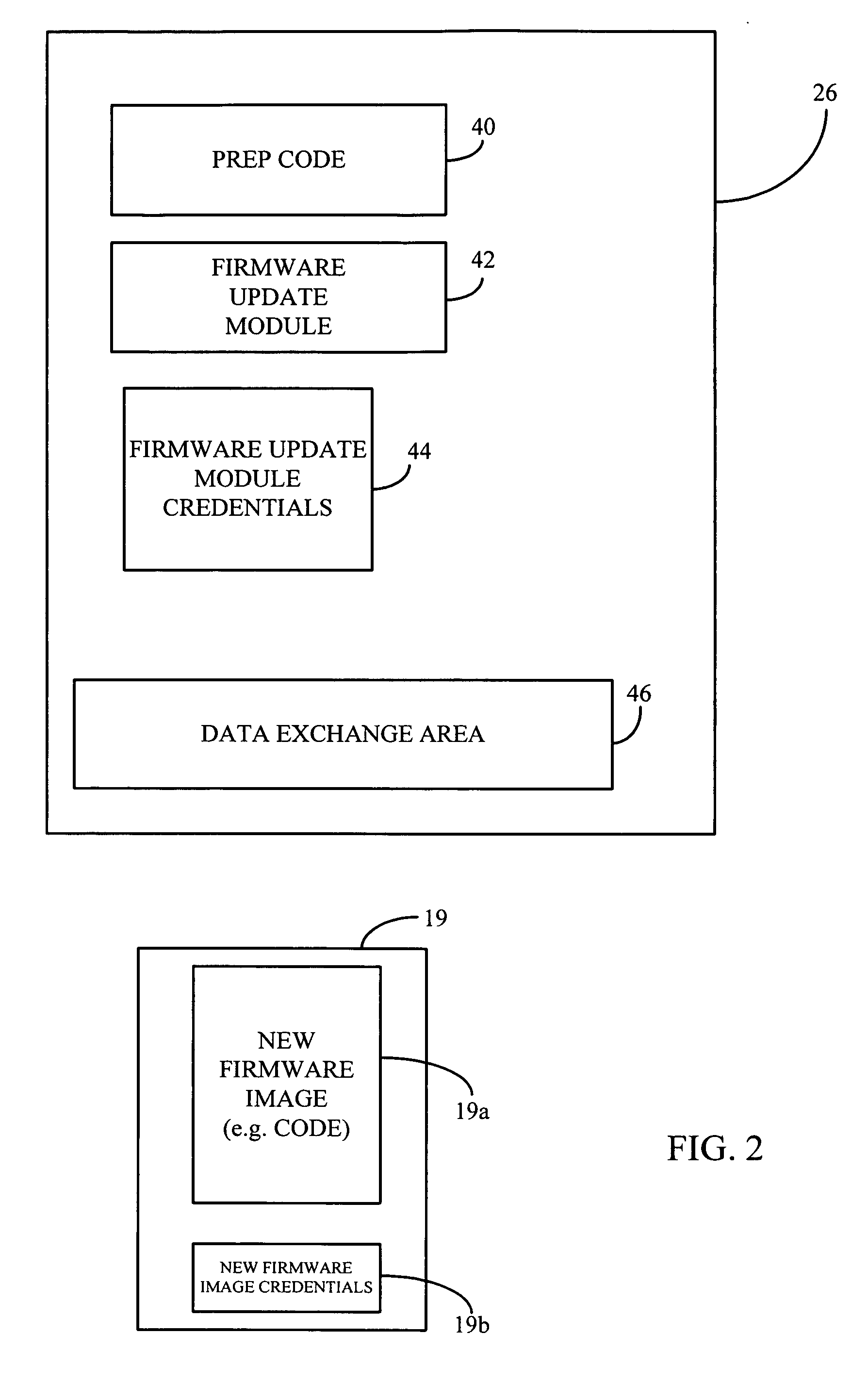
A secure firmware update method includes receiving a firmware update image, for example, firmware code including corrected or updated functionality. Next, the firmware update image and the source of the firmware update image are authenticated. After the firmware update image and the source of the firmware update image have been authenticated, the current firmware image is replaced by the firmware update image. If either of the new firmware image or the firmware update module is not authorized, the memory remains locked; thereby, preventing the unauthorized firmware image from being flashed into the memory. An electronic device includes a processor and a memory. The memory maintains instructions that when executed by the processor, causes the processor to receive a firmware update image. Next, the instructions cause the processor to authenticate the firmware update image and the source of the image. After the firmware update image and the source of the firmware update image have been authenticated, the current firmware image is replaced by the firmware update image.

Description

FIELD OF THE INVENTION [0001] The present invention generally relates to electronic devices and, more particularly, to securely updating firmware that executes on electronic devices. BACKGROUND OF THE INVENTION [0002] Electronic devices, for example, laptop computers, desktop computers, personal digital assistants (PDA's), Internet appliances, embedded devices, for example, routers and set-top boxes, wireless communication devices and other similar devices and combinations thereof typically include a controller (e.g. central processing unit) and a non-volatile or read only memory (ROM) which contains firmware or other suitable code that is executed by the controller. When the electronic device is initially powered up, a special ROM based program, for example, Basic Input / Output System (BIOS) code is handed control of the electronic device by the controller. [0003] The BIOS is responsible for initializing and configuring the various hardware subsystems, for example, display controlle...

Claims


Application Information

Patent Timeline
IPC IPC(8): G06F9/44
CPCG06F21/572
Inventor COTTRELL, ANDREWBETHUR, JITHENDRAMARKEY, TIMOTHY J.SRIKANT, M.SRINIVASAN, LAKSHMANAN
Owner KINGLITE HLDG INC
Learn More