
Active assist for the ankle, knee and other human joints

a technology for human joints and ankles, applied in the field of human joint support systems, can solve the problems of affecting the stability of the joint, so as to reduce the tensional and torque related load and reduce the load

Inactive Publication Date: 2006-06-29
IAROCCI MICHAEL ANTHONY
View PDF6 Cites 50 Cited by
  • Summary
  • Abstract
  • Description
  • Claims
  • Application Information

AI Technical Summary

Benefits of technology

"The present patent describes a device for assisting with joint movement in the human body. The device applies a concentrated torque to the joint to reduce the risk of injury and re-injury. It also relieves stress on surrounding muscles, tendons, and ligaments associated with joint movement. The device can adjust its assist level and is useful for joint rehabilitation and sports activities. It includes a hinge mechanism and an assist member that stores energy to assist in joint movement. The device helps the body return to its initial position and reduces the need for physiological torque."

Problems solved by technology

The knee joint is the fulcrum of the body's longest lever and is subjected to tremendous bending moments and loads during athletic activity.
As a result, these vulnerable joints are sites of many injuries.
The tension applied via this system results in an application of torque at the joint, which tends to straighten (extend) the leg from a flexed position around the knee.
This can occur, for example, when the tension supplied by the muscle is too great.
(Sudden impacts to the muscles and / or connective tissue (such as unexpectedly stepping off a curb or into a hole) can also result in ruptures or injuries.)
Such devices, however, providing support and restraint, are passive.
Thus, the devices do not serve to reduce the force on the muscles, tendons, etc. created by such activity and which can result in injury.
Especially in a rehabilitation case, these forces can result in injury to the tendon, ligament and / or muscle, as described above.

Method used


Image

  • Active assist for the ankle, knee and other human joints
  • Active assist for the ankle, knee and other human joints
  • Active assist for the ankle, knee and other human joints

Examples


Embodiment Construction

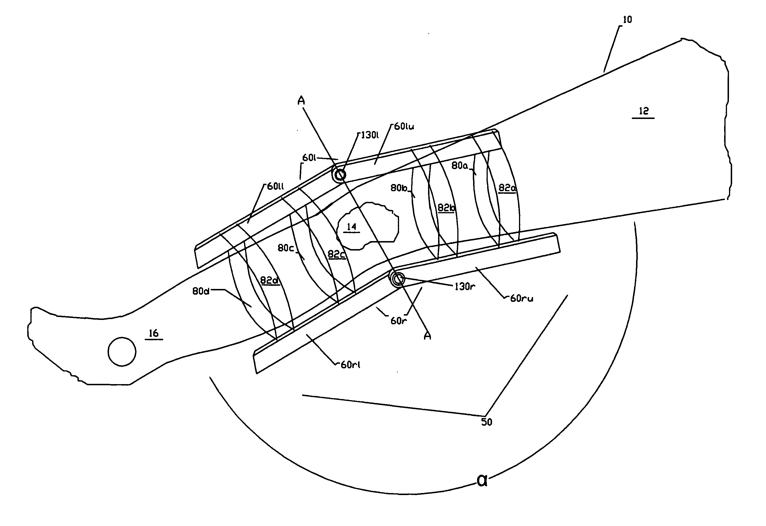
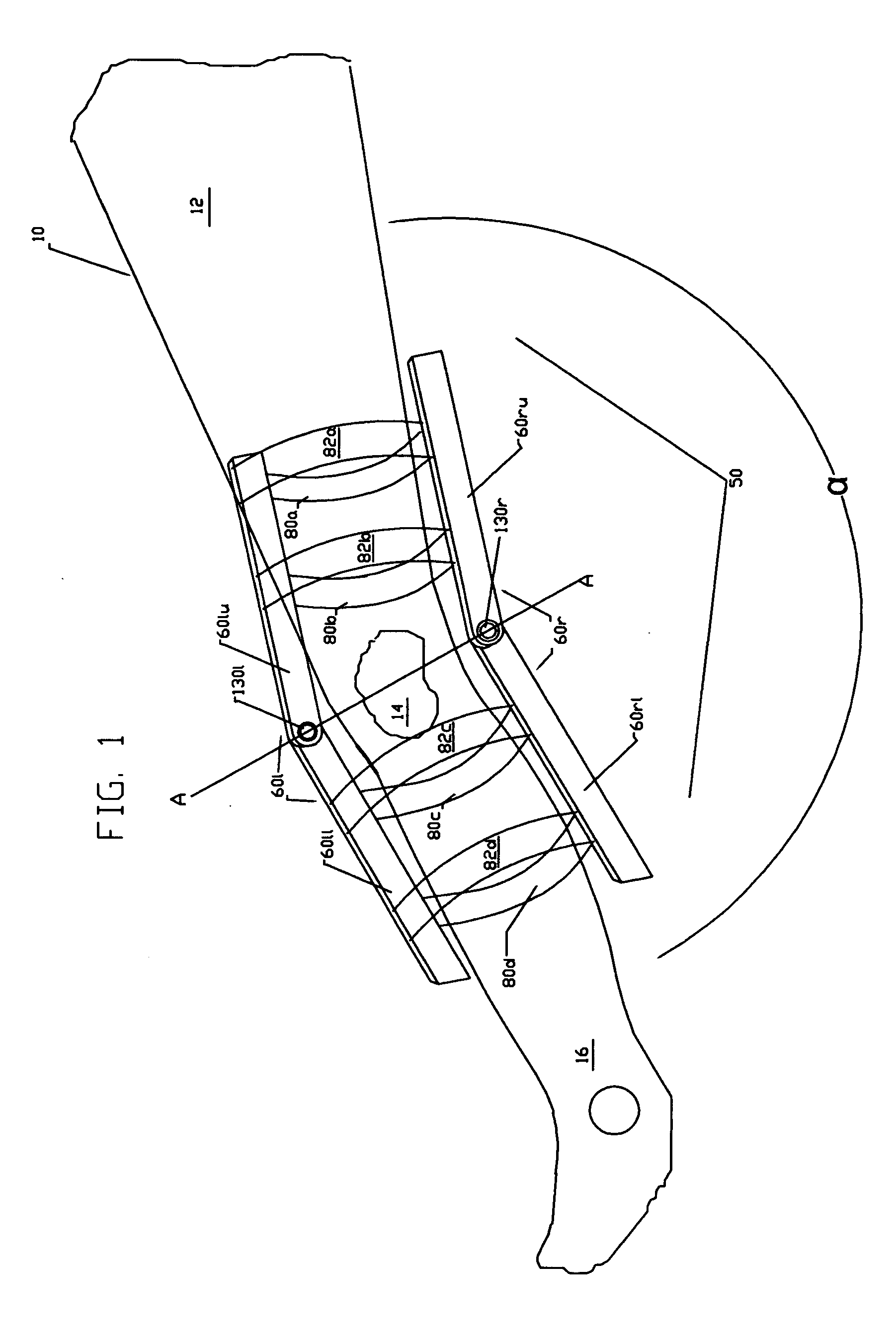
[0030] Embodiments of the presently described assist brace will now be described with reference to the accompanying drawings, in which like reference numbers designate identical or corresponding elements in each of the views.

[0031] With initial reference to FIG. 2 an exemplary embodiment of an assist brace in accordance with the present disclosure is shown and generally designated as 100. The assist brace 100 in the exemplary embodiment is for the knee, although as described below, the invention can be applied in a device for any joint.

[0032] Assist brace 100 includes two support members 160l, 160r that lie on the left and right sides of the person's leg, respectively, as shown in FIG. 2. (Although not shown in FIG. 2, the person's leg would be situated in device 100 in the same manner as the leg 10 is situated in the brace 50 in FIG. 1, namely, with the axis of the knee joint aligned with axis A-A.) Left support member 160l is comprised of left upper support portion 160lu and lef...


PUM


Abstract

A human joint assist device that applies a torque at the joint to assist physiological exertion forces, that is the load carrying task of the joint and surrounding muscles, tendons, and ligaments. The application of this device reduces the physiological exertion force requirement, and may be adjusted with respect to assist level, to suit the issue associated with joint motion and is useful for joint rehabilitation and sports activities. Among other things, this results in a reduction of physiological exertion force in a fashion that makes it easier to extend the levers (long bones) associated with extension against a given resistance. For example, standing from a squatted position with the assist of this device reduces the stress on physiological members associated with joint articulation.

Description

CROSS-REFERENCE TO RELATED APPLICATIONS [0001] None BACKGROUND [0002] 1. Technical Field [0003] The present disclosure relates to human joint support systems. More particularly, the present disclosure relates to a device that supports human joints and adds the additional feature of providing torque at the fulcrum point to assist or compliment motion. [0004] 2. Background of Related Art [0005] The knee joint is often described as the largest and most complex joint in the human body. The knee joint is the fulcrum of the body's longest lever and is subjected to tremendous bending moments and loads during athletic activity. The ankle joint is also a fulcrum, of the hinge-type and diathrotic (freely moveable), subjected to large bending moment forces. As a result, these vulnerable joints are sites of many injuries. As a one-axial joint, movements of the knee are primarily restricted to flexion and extension; the fully extended knee corresponds to a straight leg where the angle measured o...

Claims


Application Information

Patent Timeline
Patent Type & Authority Applications(United States)
IPC IPC(8): A61F5/00
CPCA61F5/0125A61F2005/0179
Inventor IAROCCI, MICHAEL ANTHONY
Owner IAROCCI MICHAEL ANTHONY
Learn More