Apparatus and Method for Loading and Unloading Cargo

a cargo and apparatus technology, applied in the direction of loading/unloading vehicle arrangment, transportation items, refuse gathering, etc., can solve the problems of not allowing the ramp to remain, the ramp attachment does not secure the loading surface of the cargo carrier, and the user of the ramp is injured, so as to achieve safe loading or unloading

Inactive Publication Date: 2006-06-22
DAY JOHN P
View PDF22 Cites 24 Cited by
  • Summary
  • Abstract
  • Description
  • Claims
  • Application Information

AI Technical Summary

Benefits of technology

[0006] The present invention discloses an apparatus that securely positions ramps to the loading surface of a cargo carrier thereby reducing the number of injuries to persons and cargo caused by accidental ramp slippage.
[0007] The present invention discloses an apparatus having ramps attached thereto which reduces the likelihood of theft of the ramps when such ramps are not in use.
[0008] The present invention discloses an apparatus that prevents the theft of equipment, all terrain vehicles, rideable work vehicles, such as lawnmowers, motorcycles, snowmobiles, etc. carried in the truck bed of a pickup truck or in a trailer when the apparatus is in the transport position because the apparatus prevents the tailgate of the pickup truck or trailer from being opened.

Problems solved by technology

These means of attachment do not safely secure the ramps to the loading surface of a cargo carrier.
Upon use, the ramps are prone to accidental slippage thereby causing injury to the user of such ramps and to the cargo being loaded or unloaded.
Additionally, these means of attachment do not allow for the ramps to remain outside of the moving vehicle during transport of the cargo.
It is common for unattached ramps to be stolen from truck beds when such ramps are not in use.

Method used


Image

  • Apparatus and Method for Loading and Unloading Cargo
  • Apparatus and Method for Loading and Unloading Cargo
  • Apparatus and Method for Loading and Unloading Cargo

Examples


Embodiment Construction

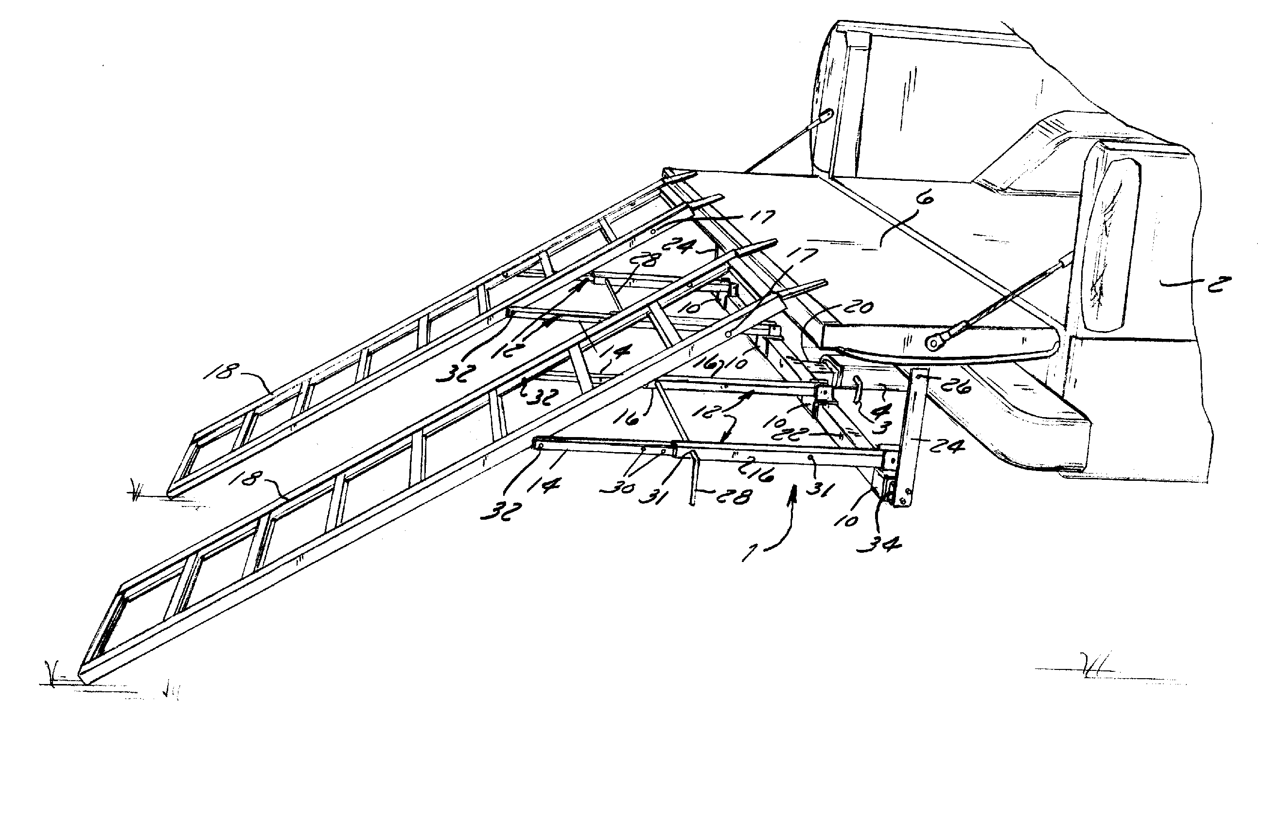
[0031] Referring now to FIG. 1, the present invention discloses an apparatus 1 for securing a ramp 18 to a cargo carrier 2.

[0032] Now referring to FIGS. 1-2, the apparatus 1 is made of an engaging member 20, cross support 22, at least two locking members 24, and a plurality of telescopic arms 12. The engaging member 20 is configured to engage the receiver hitch 4 which is permanently attached to cargo carrier 2. The cross support 22 is preferably attached perpendicularly to the engaging member 20 by welding but other means of attachment may be used as desired by one of skill in the art (see FIG. 3A). Locking members 24 extend vertically from cross support 22 (see FIG. 3A).

[0033] Cross support 22 has a plurality of mounting brackets 10 mounted thereto. Mounting brackets 10 are hollow and slide onto cross support 22 before locking members 24 are attached to cross support 22. Mounting brackets 10 are adjustable across the length of cross support 22 to accommodate widths of varying ra...


PUM


Abstract

An apparatus and method for securing a ramp to a cargo carrier having a receiver hitch and a loading surface are disclosed. The apparatus comprises an engaging member configured to engage the receiver hitch of the cargo carrier; a cross support attached to the engaging member, wherein the cross support has a plurality of mounting brackets mounted thereto; at least two locking members attached to opposite ends of the cross support and extend vertically therefrom, wherein each locking member has an aperture configured to slideably receive a ramp locking pin; and a plurality of telescopic arms attached to the mounting brackets, wherein each telescopic arm has an inner portion and an outer portion, wherein the outer portion and inner portion have at least one set of apertures for slideably receiving a ramp locking pin, wherein the inner portion is configured to attach to at least one ramp.

Description

FIELD OF THE INVENTION [0001] This invention relates to an apparatus for securing a ramp to a cargo carrier, such as a moving vehicle or trailer. BACKGROUND OF THE INVENTION [0002] Since the need to transport cargo, there has been a need for a ramp to load and unload the cargo transported in cargo carriers, such as moving vehicles or trailers. In the past, one common method of securing a loading ramp to a pickup truck to load or unload cargo comprises placing one end of a conventional ramp on the ground and the other end to the loading surface, which is typically the topside portion of an opened tailgate of a truck or sports utility vehicle. Such conventional ramps are attached to the loading surface by chains, cables or other means of attachment. [0003] These means of attachment do not safely secure the ramps to the loading surface of a cargo carrier. Upon use, the ramps are prone to accidental slippage thereby causing injury to the user of such ramps and to the cargo being loaded ...

Claims


Application Information

Patent Timeline
IPC IPC(8): B60P1/43
CPCB60P1/43
Inventor DAY, JOHN P.
Owner DAY JOHN P
Why Eureka
Try Eureka