Eureka AIR delivers breakthrough ideas for toughest innovation challenges, trusted by R&D personnel around the world.

Image forming device, image forming method, and computer readable recording medium stored with image forming program

a technology of image forming and recording media, applied in the direction of instruments, digital output to print units, visual presentations, etc., can solve the problems of increasing printing costs, increasing consumption of expensive paper provided with ic tags, etc., and reducing the consumption amount of expensive recording media, the effect of curbing the rise of printing costs

Inactive Publication Date: 2006-06-22
KONICA MINOLTA BUSINESS TECH INC
View PDF8 Cites 32 Cited by
  • Summary
  • Abstract
  • Description
  • Claims
  • Application Information

AI Technical Summary

Benefits of technology

[0009] It is another object of the present invention to provide an image forming device, an image forming method, and a computer readable recording medium stored with an image forming program capable of providing visual and digital information simultaneously while suppressing the increase of printing cost.
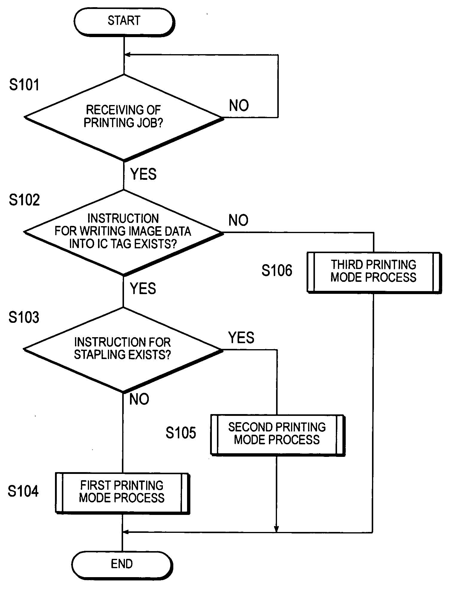
[0011] This invention makes it possible to reduce the consumption amount of expensive recording media provided with IC tags. Therefore, it enables us to curb the rise of printing cost while maintaining both visual and digital information simultaneously by a bundling process.

Problems solved by technology

However, the abovementioned image forming devices had a problem that they select and use paper provided with an IC tag each time when they receive an instruction to write data into an IC tag, which results in an increase in the consumption of expensive paper provided with an IC tag, which in turn resulting in the increase of printing cost.

Method used


Image

  • Image forming device, image forming method, and computer readable recording medium stored with image forming program
  • Image forming device, image forming method, and computer readable recording medium stored with image forming program
  • Image forming device, image forming method, and computer readable recording medium stored with image forming program

Examples


first embodiment

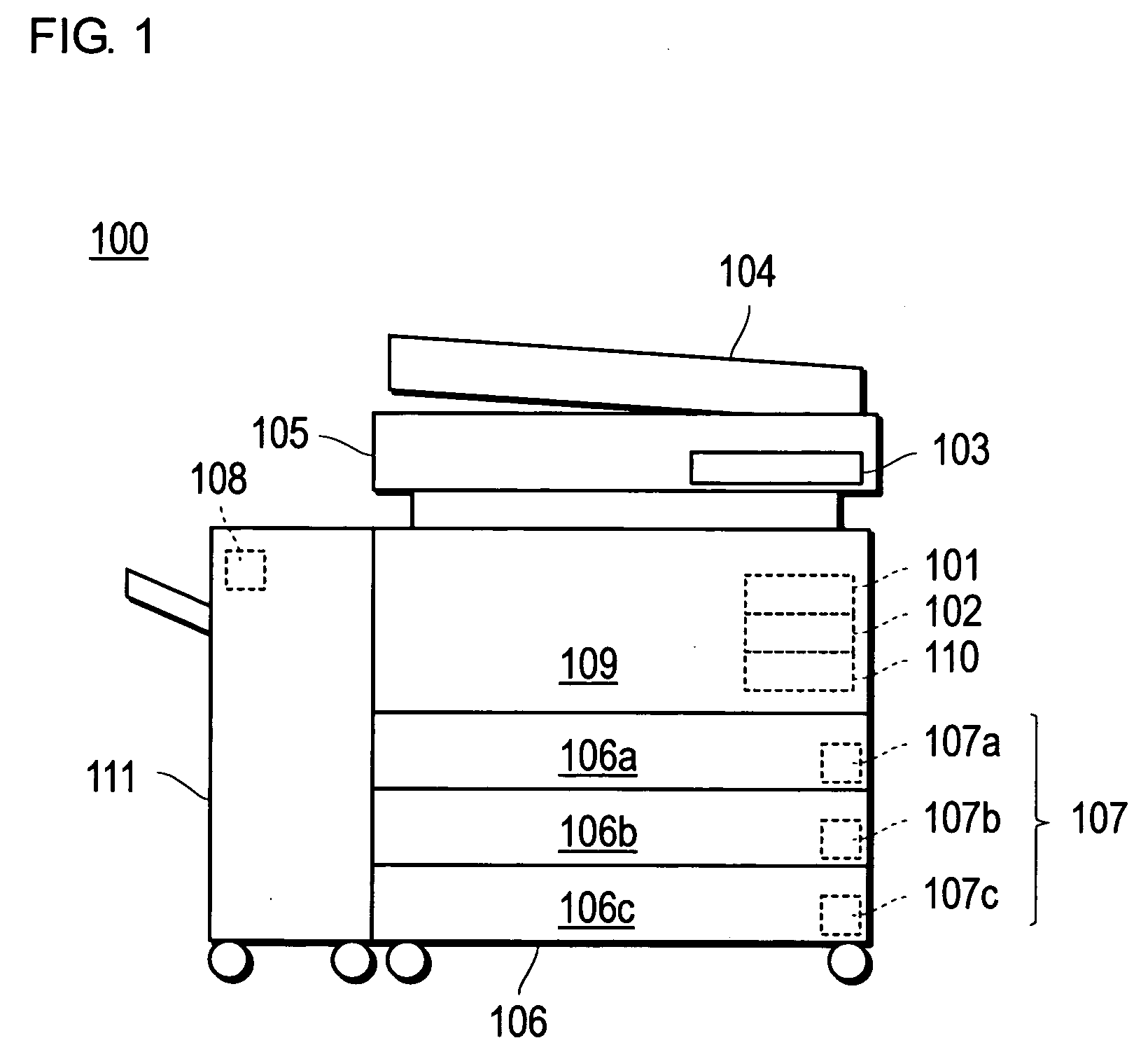
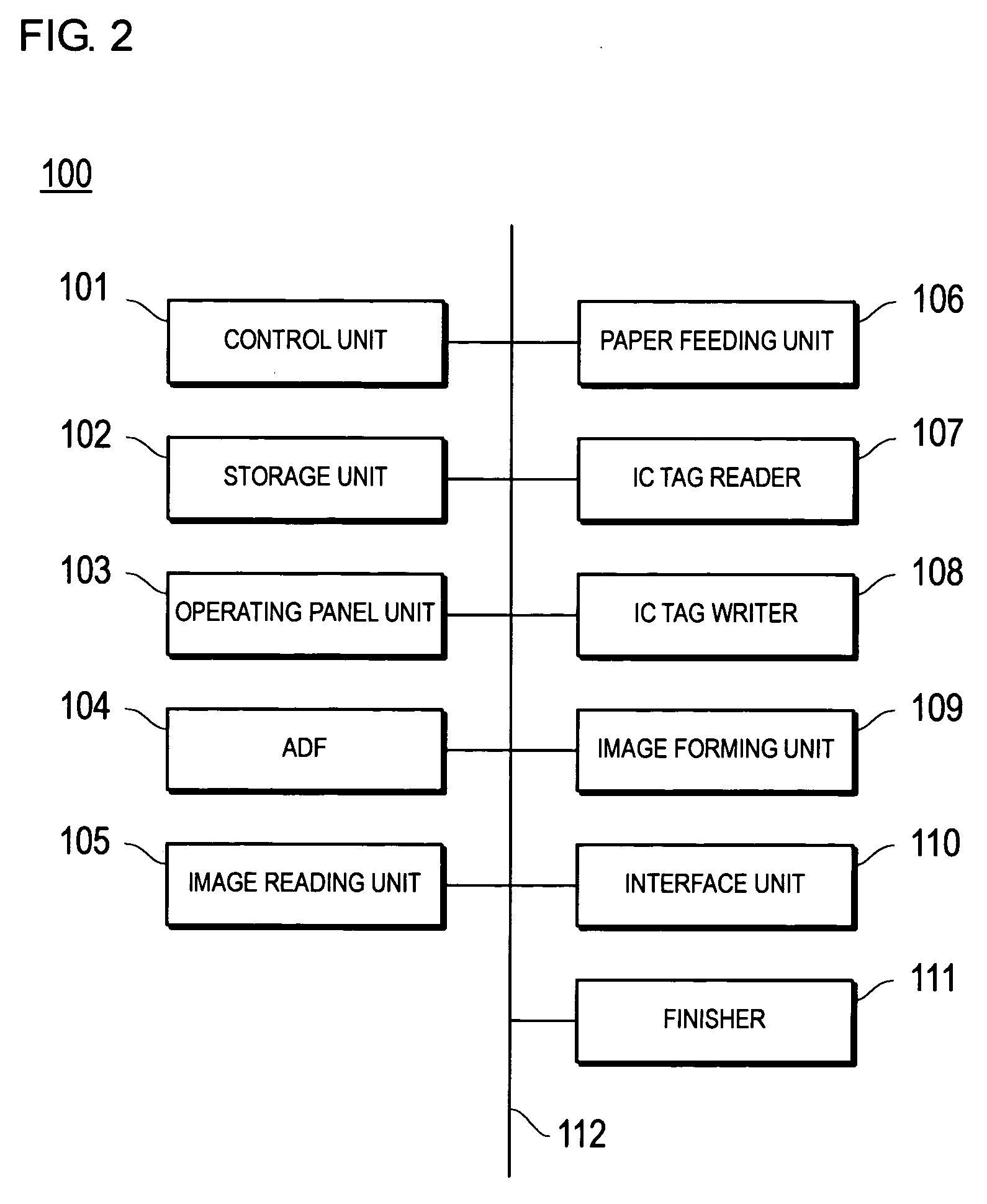
[0036]FIG. 1 is a schematic front view showing the constitution of a MFP (Multi-Function Peripheral), which serves as an image forming device according to the present invention and FIG. 2 is a block diagram showing the constitution of the MFP shown in FIG. 1.

[0037] MFP 100 is equipped with a control unit 101, a storage unit 102, an operating panel unit 103, an ADF (Auto Document Feeder) 104, an image reading unit 105, a paper feeding unit 106, an IC tag reader 107, an IC tag writer 108, an image forming unit 109, an interface unit 110, and a finisher 111, all of which are interconnected via a bus 112 for exchanging signals with each other.

[0038] The control unit 101 is a CPU, and controls various parts indicated above and executes various arithmetic processes according to a program. The storage unit 102 consists of a ROM for writing various programs and data, a RAM for temporarily writing programs and data as a working area, a hard disk for writing various programs and data includi...

second embodiment

[0075]FIG. 10 is a flowchart showing the sequence of a second printing mode process concerning the invention. The algorithm shown in the flow chart of FIG. 10 is stored as a program in the storage unit 102 of the MFP 100 and executed by the control unit 101.

[0076] In the second printing mode process of the second embodiment, a judgment is made as to whether any image data that have not been written into the IC tag or not (S501). The data is written into the IC tag from the image data of the first page followed by image data of other pages in the descending order of the pages.

[0077] If there is any data that has not been written into the IC tag (S501: Yes), the IC-tagged paper will be selected as paper to be used for printing pages to be processed (S502). For example, the object of the process in the initial stage is the first page and the image data is not yet written into the IC tag, the IC-tagged paper will be selected as the paper for printing the first page. After the IC-tagged...

third embodiment

[0086]FIG. 13 is a flowchart showing the sequence of a second printing mode process concerning the invention. The algorithm shown in the flow chart of FIG. 13 is stored as a program in the storage unit 102 of the MFP 100 and executed by the control unit 101.

[0087] In the second printing mode process of the third embodiment, only the IC-tagless paper will be selected as the paper for printing (S601). Next, the entire image data contained in the printing job is printed on paper page by page (S602). The processing of these steps S601 through S602 is repeated until all the pages are printed (S603: No), and the program returns to the step 604 when all the pages are printed (S603: Yes).

[0088] The bundle of the printed paper is stapled in the step S604. Next, the entire image data to be printed on multiple sheets of paper is written into the IC tag built into the staple (S605) and the program returns to the flowchart of FIG. 4.

[0089]FIG. 14 shows a schematic view of a bundle of paper obt...


PUM


Abstract

An image forming device makes a judgment on whether a bundling process for bundling a plurality of printed recording media is instructed or not, when a process for writing image data to be printed on the recording media into an electronic tag is instructed. The device selects only recording media each provided with an electronic tag as the recording media for printing and writes image data to be printed on each recording medium into the electronic tag of the corresponding recording medium, when the bundling process is not instructed. The device selects a recording medium provided with an electronic tag and a recording medium provided with no electronic tag as the recording media for printing and writes into the electronic tag of the recording medium with the electronic tag the entire image data to be printed on a plurality of recording media, when the bundling process is instructed.

Description

[0001] This application is based on Japanese Patent Application No. 2004-369391 filed on Dec. 21, 2004, the contents of which are hereby incorporated by reference. BACKGROUND OF THE INVENTION [0002] 1. Field of the Invention [0003] The invention relates to an image forming device, an image forming method, and a computer readable recording medium stored with an image forming program. The invention relates particularly to an image forming device, an image forming method, and a computer readable recording medium stored with an image forming program capable of writing into an IC tag provided on paper image data for printing on paper. [0004] 2. Description of the Related Art [0005] An image forming device is disclosed (refer to Unexamined Publication No. JP-A-2002-337426) for printing images on paper based on data received from external equipment such as a PC (personal computer) as well as for writing data into an IC tag, if the received data contains some data to be written into the IC ...

Claims


Application Information

Patent Timeline
Patent Type & Authority Applications(United States)
IPC IPC(8): G06F3/12
CPCB41J3/44B41J11/485G06K15/00G06K17/00G06K17/0025G06K2215/0082G06K15/1809G06K15/1823
Inventor YAMAMOTO, KAZUTOKIWADA, MASAKATSU
Owner KONICA MINOLTA BUSINESS TECH INC
Why Eureka
Eureka Blog
Learn More