Low thermal resistance junction processing

a junction processing and low thermal resistance technology, applied in the field of low thermal resistance junction processing, can solve the problems of ineffective reduction of thermal resistance in compression-type junctions, and limited improvement of thermal resistance across the junction, so as to reduce junction thermal resistance, enhance structural strength and air tightness

Inactive Publication Date: 2006-06-22
LEE FREDERICK
View PDF0 Cites 0 Cited by
  • Summary
  • Abstract
  • Description
  • Claims
  • Application Information

AI Technical Summary

Benefits of technology

[0007] The primary purpose of the present invention is to provide a method for reducing junction thermal resistance so that two identical or different types of metallic material could be bound together with enhanced structural strength and airtightness.
[0008] To achieve the foregoing objectives, the present invention mainly forms a capillary structure at the junction between two identical or different types of metallic material. The present invention then adds an appropriate amount of soldering paste at the junction. The soldering paste is then melted to bind the two types of material together. Due to the capillarity effect, the melted soldering paste has better wettability on the metallic surfaces so that the melted soldering paste flows and distributes more uniformly at the junction. When the temperature drops, the junction could achieve a better structural strength and airtightness. The junction's thermal resistance is thereby reduced and its thermal conductivity could be fully utilized.

Problems solved by technology

However, as the surface roughness of the two types of material 101a and 101b are difficult to control, there are often voids 101c left in the junction between the two types of material 101a and 101b. As such, the thermal resistance in this compression-type junction could not be reduced effectively.
In addition, since the solder fluxes (not shown) are often depleted during the process, soldering paste 102d stays only within smaller gaps when temperature drops.
Again, there is only limited improvement to the thermal resistance across the junction and to the structural strength at the junction.

Method used


Image

  • Low thermal resistance junction processing
  • Low thermal resistance junction processing
  • Low thermal resistance junction processing

Examples


Embodiment Construction

[0026] The following descriptions are of exemplary embodiments only, and are not intended to limit the scope, applicability or configuration of the invention in any way. Rather, the following description provides a convenient illustration for implementing exemplary embodiments of the invention. Various changes to the described embodiments may be made in the function and arrangement of the elements described without departing from the scope of the invention as set forth in the appended claims.

[0027] In the following, detailed description along with the accompanied drawings is given to better explain preferred embodiments of the present invention.

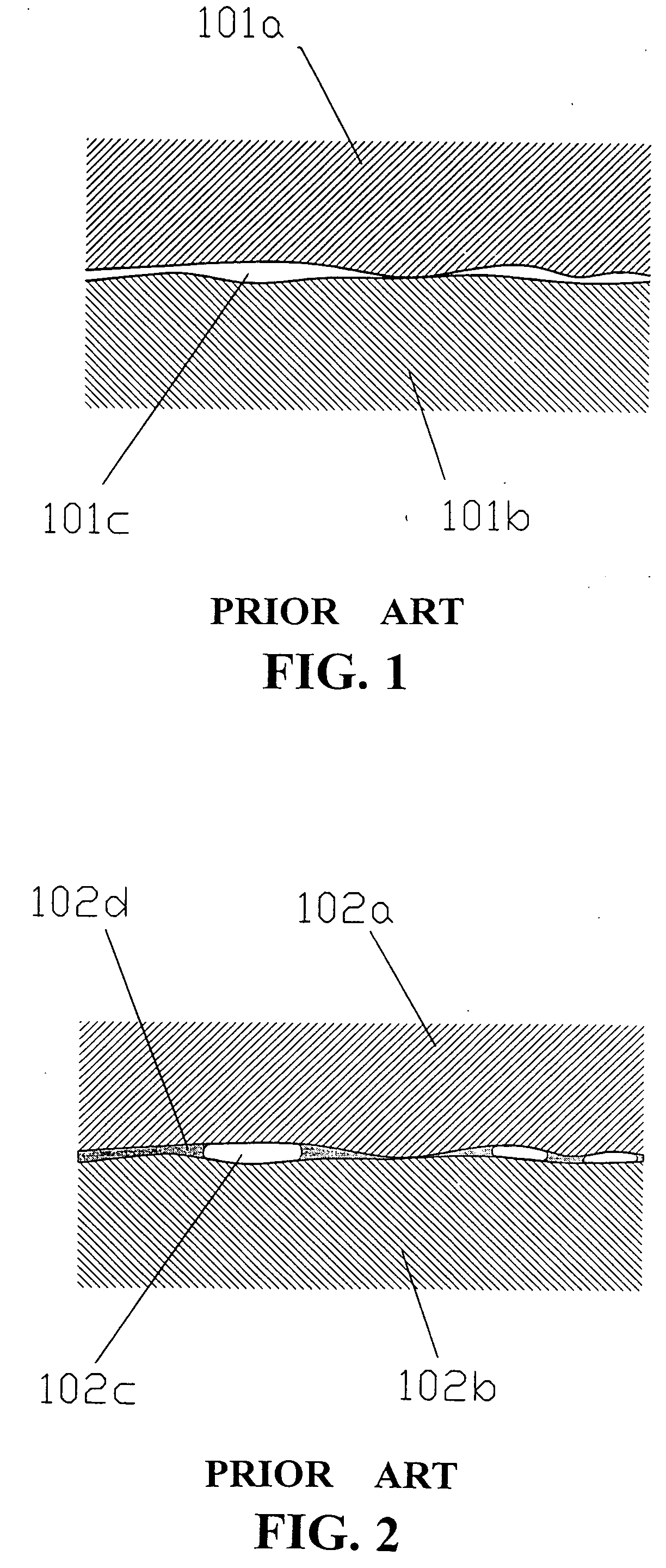
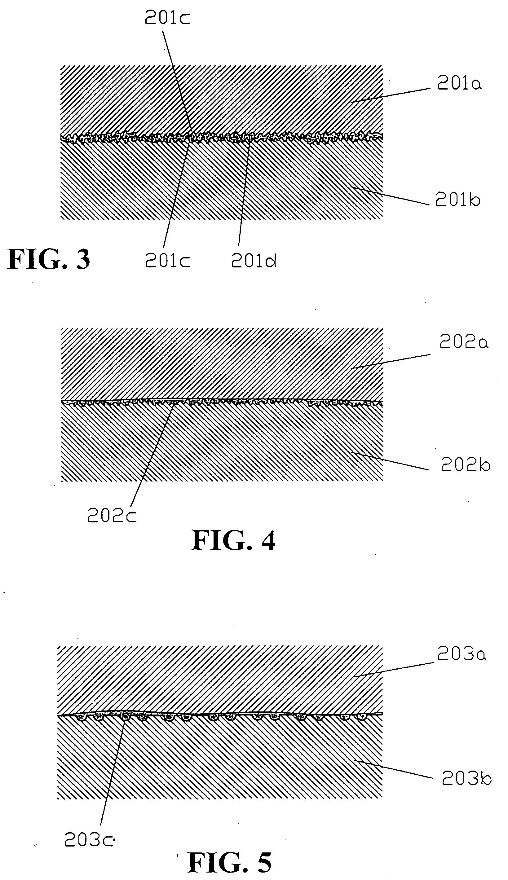
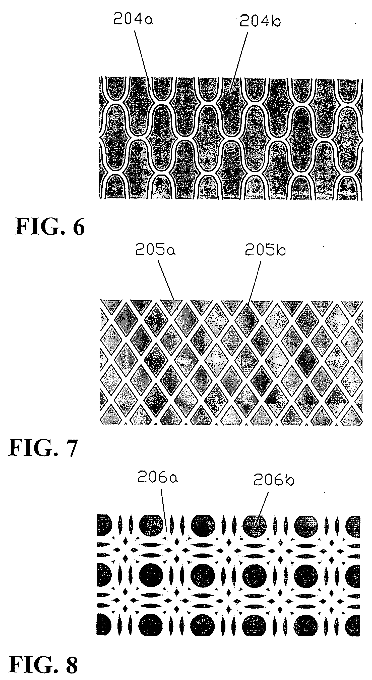
[0028] In a preferred embodiment of the present invention, a capillary structure is formed at the junction between two identical or different types of metallic material. An appropriate amount of soldering paste is then added in the junction and melted to bind the two types of material together.

[0029] The capillary structure 201c could be f...


PUM

PropertyMeasurementUnit
Temperatureaaaaaaaaaa
Capillary waveaaaaaaaaaa
Metallic bondaaaaaaaaaa

Abstract

A method for reducing thermal resistance at a junction between two types of metallic material is provided. The method mainly forms a capillary structure between the two surfaces of the two identical or different types of metallic material. The method then adds and melts an appropriate amount of soldering paste at the junction so as to bind the two types of metallic material together. The invention could achieve superior structural strength and thermal conductivity at the junction.

Description

BACKGROUND OF THE INVENTION [0001] (a) Technical Field of the Invention [0002] The present invention generally relates to metallic junctions, and more particularly to a method for reducing the thermal resistance at metallic junctions. [0003] (b) Description of the Prior Art [0004] As the performance of semiconducting chips is continuously climbing, heat dissipation has caught the attention of the chip makers and system integrators alike. Effective heat dissipation is crucial to the high performance chips' normal functioning and operation life. Well-designed heat dissipating mechanisms could also help reducing the dimensions of the electronic devices using these high performance chips, making these electronic devices smaller and lighter. Therefore, people are aggressively searching for even more effective heat dissipating technologies. [0005] When a junction is required and formed between two identical or different types of metallic material (such as copper, aluminum, etc.), there ar...

Claims


Application Information

Patent Timeline
IPC IPC(8): B23K31/00
CPCB23K1/0016B23K2201/40B23K2101/40
Inventor LEE, FREDERICK
Owner LEE FREDERICK
Why Eureka
Try Eureka