
Suspending, guiding and propelling vehicles using magnetic forces

a technology of magnetic force and vehicle, applied in the field of suspension force, can solve the problems of low speed, high cost of magnet, no suspension force, etc., and achieve the effect of high operating speed and high acceleration

Inactive Publication Date: 2006-06-22
MAGNEMOTION INC
View PDF99 Cites 27 Cited by
  • Summary
  • Abstract
  • Description
  • Claims
  • Application Information

AI Technical Summary

Benefits of technology

[0028] Systems and methods according to the invention are advantageous in many regards. Among these, is that they offer high acceleration so that high operating speed is possbile even when there are frequent stops and a need for negotiating tight turns at lower speeds.

Problems solved by technology

In spite of proven advantages, such as fast, comfortable, quiet and efficient operation, maglev has been perceived as expensive and primarily suited for very high speed operation.
Applications for urban use have been limited by the ability of proposed designs to compete effectively with conventional guided systems such as rapid transit, light rail, monorail, commuter rail and express busways.
EDS has the virtue that it can operate with a larger magnetic gap than EMS but has the fundamental disadvantage that it creates high drag at low speeds and provides no suspension force when stopped.
On the other hand, EMS has the advantage that it can operate very well at low speeds but has the disadvantage that the magnetic gap must be less than gaps that are practical with EDS designs.
This design requires the use of wheels for low speed operation and because of the high low speed drag is not well suited to low speed operation.
It does not address the issue of guidance or propulsion.
U.S. Pat. No. 3,937,148 (Virtually zeros power linear magnetic bearing; Inventor: Paul A. Simpson; Issued: Feb. 10, 1976) shows how the patent 3,860,300 can be used for transportation applications but requires separate electromagnets and does not address the issues of guidance and propulsion.
U.S. Pat. No. 4,088,379 (Variable permanent magnet suspension system; Inventor: Lloyd Perper; Issued: May 9, 1978) builds on the ideas in U.S. Pat. No. 3,860,300 but it is not directly applicable to maglev using EMS.
It is specific to EDS and does not teach how to use permanent magnets in an EMS design.
U.S. Pat. No. 6,860,300 (Virtually zero powered magnetic suspension; Inventor: Joseph Lyman; Issued Jan. 14, 1975) teaches how permanent magents can be used to provide magnetic suspension but the design disclosed requires separate electromagnets and is not readily applicable to a transportation application.
U.S. Pat. No. 3,937,148 (Virtually zeros power linear magnetic bearing; Inventor: Paul A. Simpson; Issued: Feb. 10, 1976) shows how the preceding patent can be used for transportation applications but requires separate electromagnets and does not address the guidance and propulsion.

Method used


Image

  • Suspending, guiding and propelling vehicles using magnetic forces
  • Suspending, guiding and propelling vehicles using magnetic forces
  • Suspending, guiding and propelling vehicles using magnetic forces

Examples


Embodiment Construction

[0041] Systems according to the invention can use one magnetic structure to provide suspension, propulsion and guidance. In one embodiment, the suspension can lift about ten times the weight of the magnet structure and the integrated propulsion system can operate with an average efficiency of 90% or more. A transportation system using this suspension, propulsion and guidance can have lighter vehicles, consume less energy and still have the advantage of known maglev designs, e.g., reduced noise, higher top speed, higher acceleration and lack of maintenance associated with wheel-based systems.

[0042] Choice of Dimensions

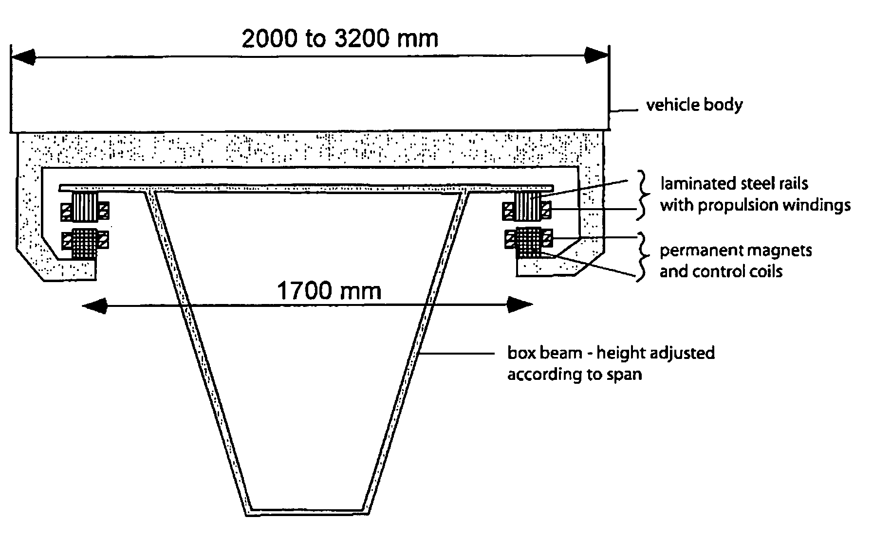
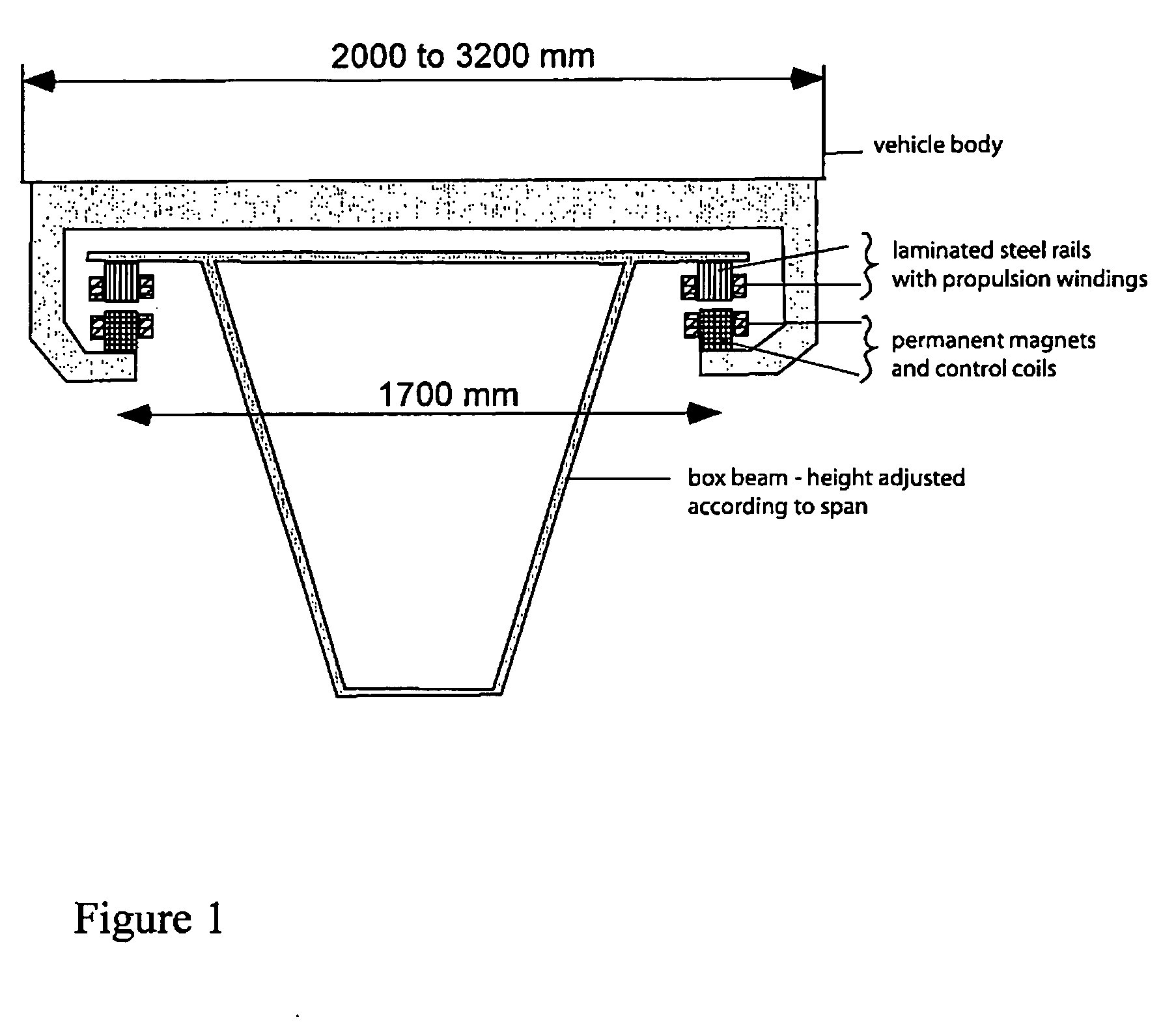
[0043]FIG. 1 shows a cross-section of the baseline suspension design in a system according to the invention. The vehicle is supported by a string of magnets on each side and these magnets create attractive forces to the laminated steel rails on the guideway. The dimensions shown in FIG. 1 were chosen with several factors in mind, e g., [0044] The vehicle width should ...


PUM


Abstract

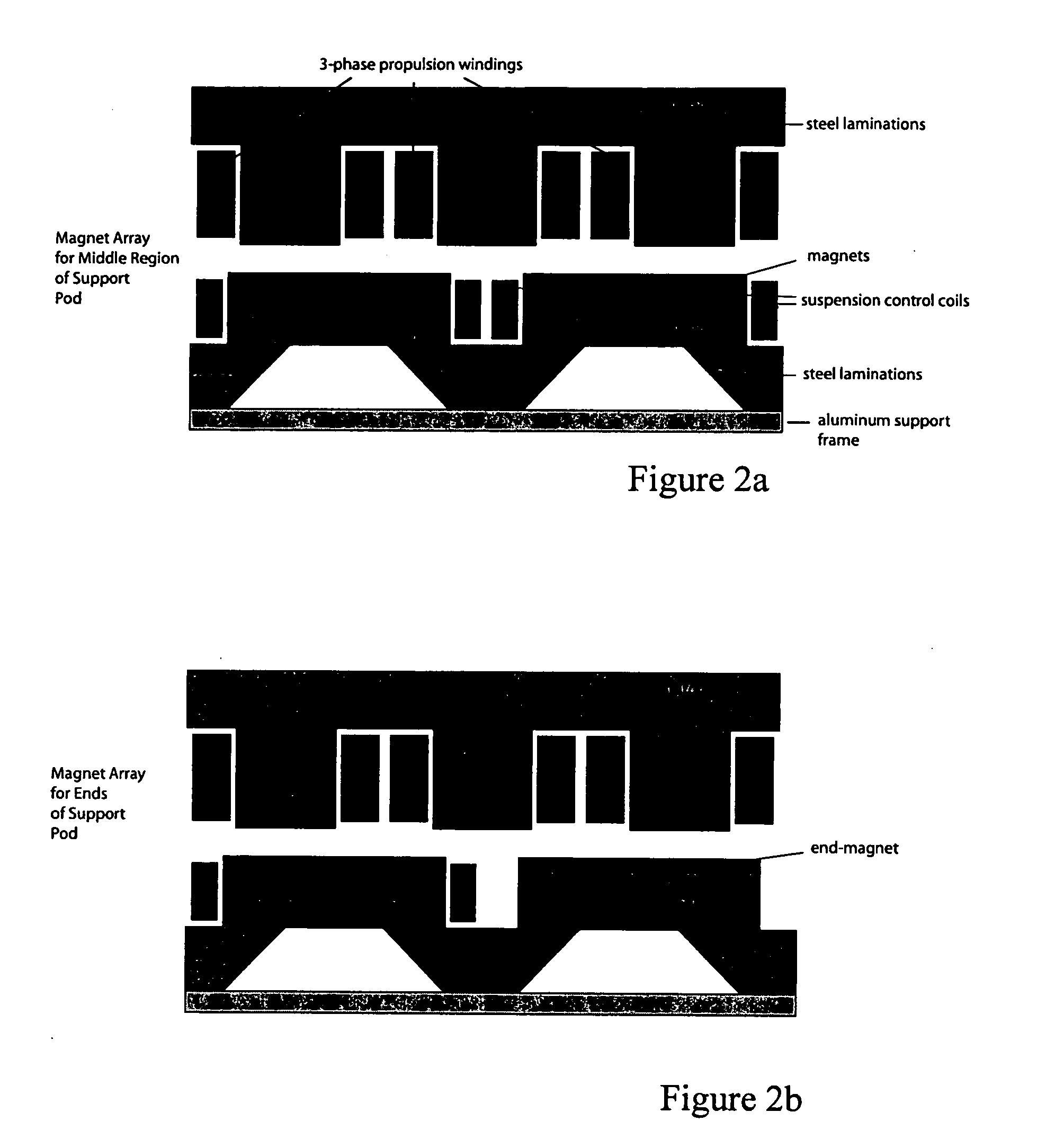
Magnetic levitation methods and apparatus use arrays of vehicle magnets to provide three forces: suspension, guidance and propulsion. The magnets, which can be permanent magnets or superconducting magnets operating in the persistent current mode, have associated control coils that allow the magnets to provide a controllable attractive force to a laminated steel rail. The control coils adjust the gap between the magnets and the rails so as to be in stable equilibrium without requiring significant power dissipation in the control coils. These same magnets and steel rails also provide lateral guidance to keep the vehicle on the track and steer the vehicle on turns. The suspension control coils can provide lateral damping by means of offset magnets in the suspension arrays. Windings in transverse slots in the steel rails are excited with currents that react against the field produced by the vehicle magnets to create vehicle propulsion. The magnet size is adjusted to provide negligible cogging force even when there are as few as three winding slots per wavelength along the rail. Means are used to mitigate end effects so that a multiplicity of magnet pods can be used to support the vehicle.

Description

[0001] This application claims the benefit of priority of U.S. Provisional Application Ser. No. 60 / 415,013, filed Oct. 1, 2002, entitled “Suspending, Guiding and Propelling Vehicles Using Magnetic Forces.” This application is a continuation-in-part of U.S. application Ser. No. 10 / 262,541, filed Oct. 1, 2002, entitled Synchronous Machine Design and Manufacturing. The teachings of the foregoing applications are incorporated herein by reference.BACKGROUND OF THE INVENTION [0002] This invention pertains to magnetic levitation (“maglev”) transportation systems and methods, and more particularly, those for suspending, guiding and propelling vehicles using magnetic forces. [0003] The use of magnetic forces to suspend, guide and propel vehicles has been extensively researched and several full size demonstration prototypes have been built. In spite of proven advantages, such as fast, comfortable, quiet and efficient operation, maglev has been perceived as expensive and primarily suited for v...

Claims


Application Information

Patent Timeline
Patent Type & Authority Applications(United States)
IPC IPC(8): B60L13/06H02G3/32H02K1/00
CPCB60L13/06B60L2200/26H02G3/32
Inventor THORNTON, RICHARD D.CLARK, TRACY M.
Owner MAGNEMOTION INC
Learn More