
Side handle for a hand-held power tool

Active Publication Date: 2006-06-22
HILTI AG
View PDF12 Cites 6 Cited by
  • Summary
  • Abstract
  • Description
  • Claims
  • Application Information

AI Technical Summary

Benefits of technology

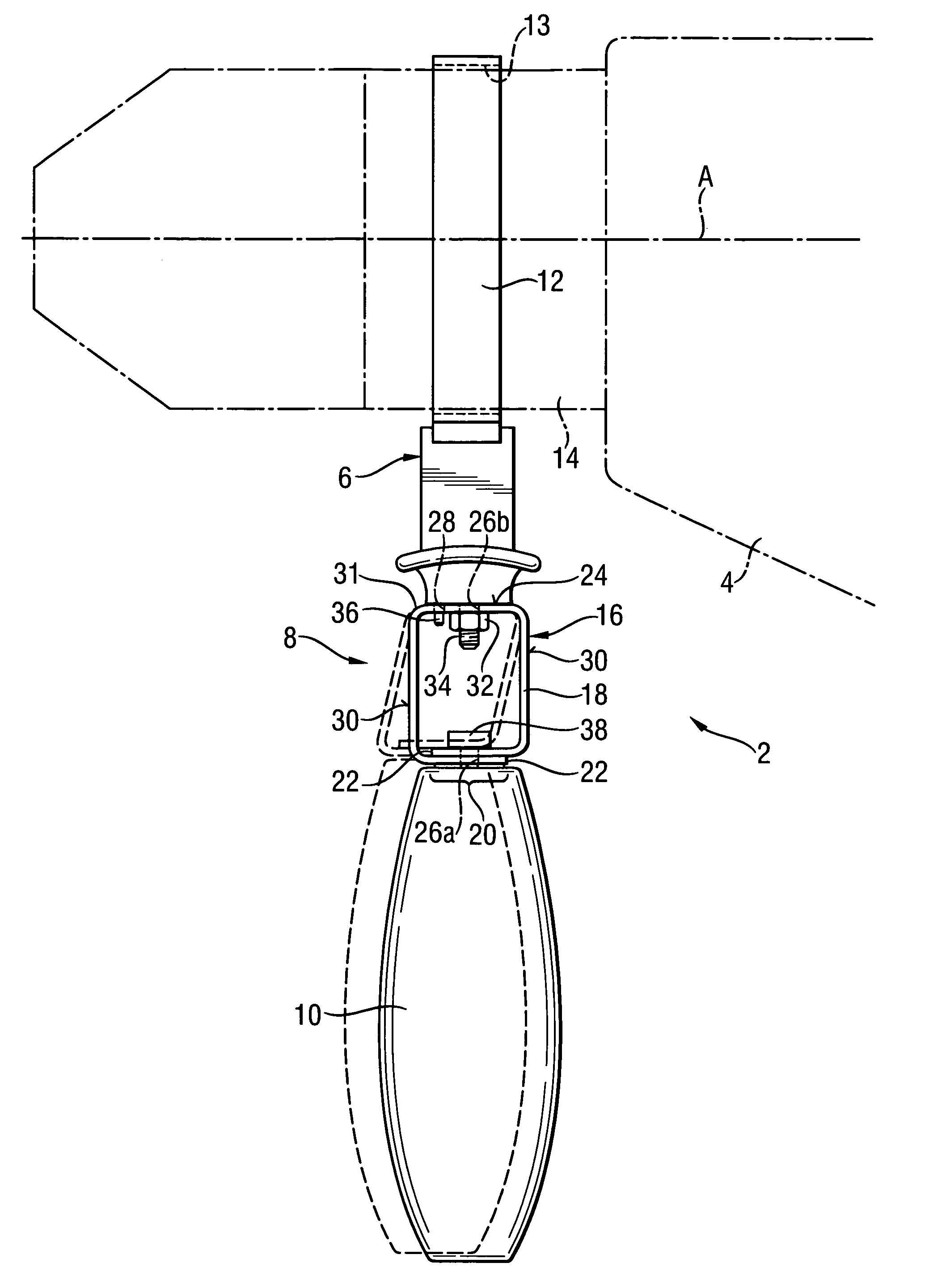
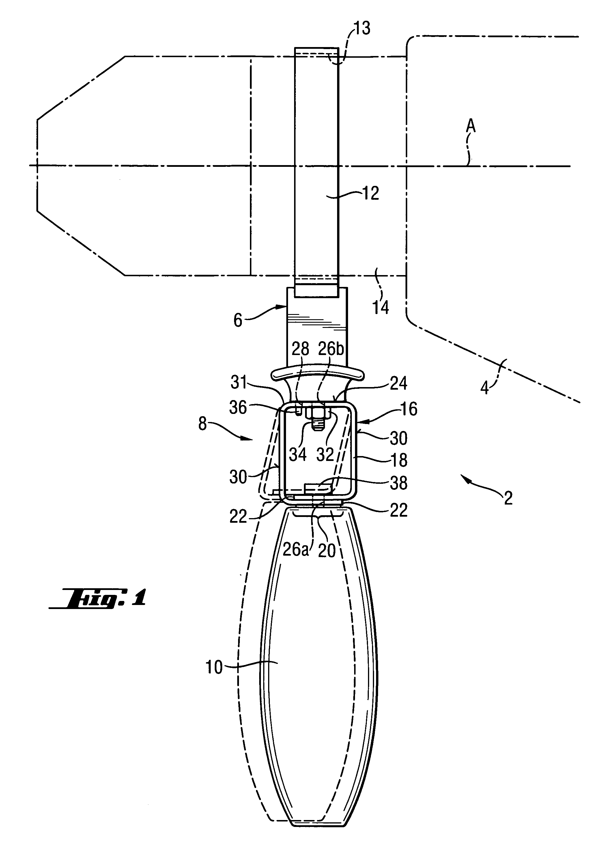
[0011] The decoupling device according to the present invention insures a constructively simple decoupling of the handle holder from the attachment device, while the swinging elements of the decoupling device, which are deflected parallel to each other, provide for a reliable guidance of the handle holder In addition, during a forceful displacement of the handle holder by the swinging elements relative to the attachment device, the handle holder retains the same alignment relative to the attachment device or to the power tool. This insures a stable guidance of the power tool, together with a substantially reduced transmission of vibrations to the handle holder. The decoupling device according to the present invention can be made very compact so that it can be easily integrated into the side handle. During an operation of the power tool, no hindrance to the operation, e.g., as a result of tilting of the decoupling device, occurs. All in all, there is provided a side handle having small manufacturing costs and which insures, at the same time, a comfortable handling of the power tool during the operation of the power tool.
[0012] Advantageously, the attachment device includes a strap retainer that defines a receiving axis for the power tool. The swinging elements of the decoupling device extend perpendicular to the receiving axis. Thereby, a decoupling for a number of power tools, in particular such as hammer drills and chisel hammers, can be achieved, in particular exactly in the direction of the main vibration axis of the power tool. This insures a substantial reduction of vibrations that are applied to the handle holder.
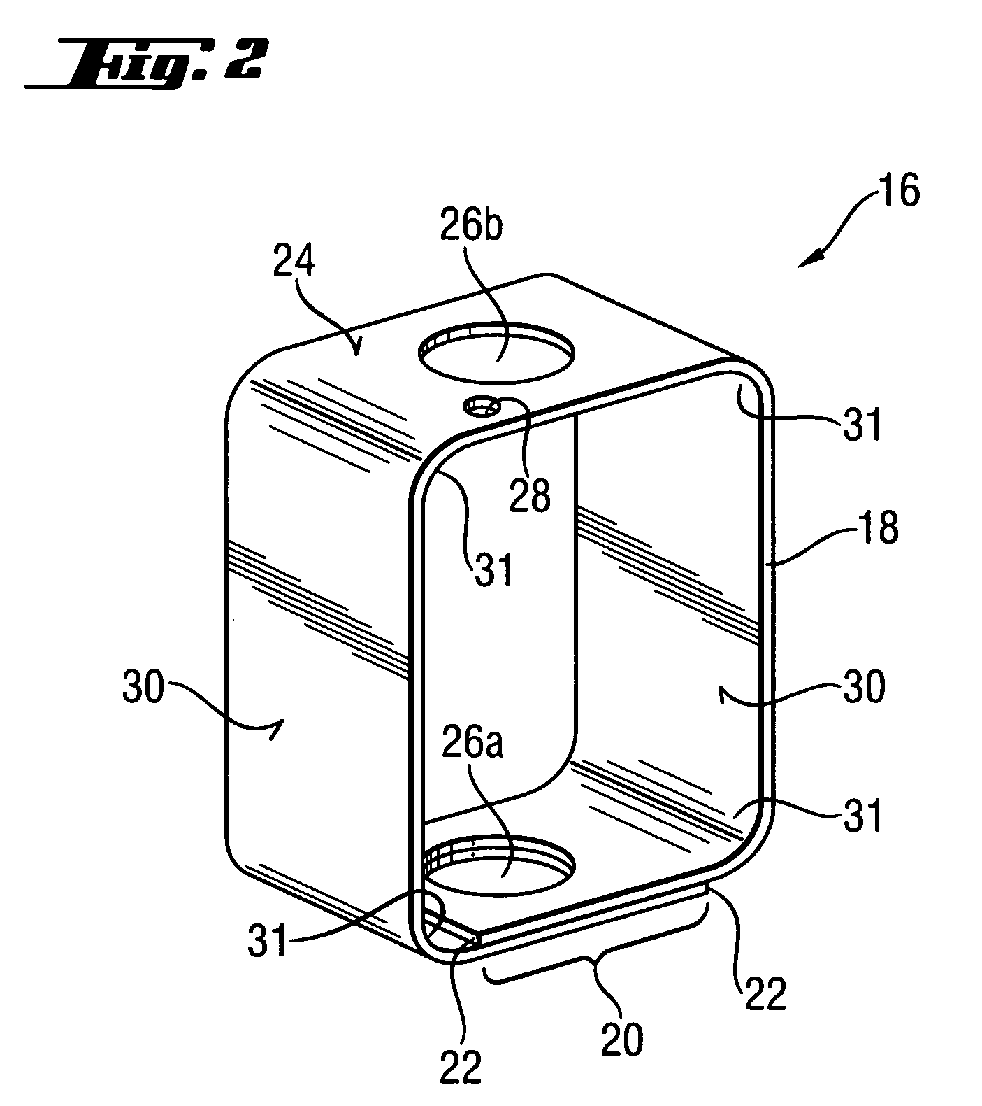
[0014] According to a particularly advantageous embodiment of the present invention, the swinging elements are formed by opposite walls of a four-side spring member that forms part of the decoupling device. Thereby, both swinging elements are formed by a single common spring member. Thereby, a particularly precise parallel kinematics can be achieved upon deflection of the swinging elements. In addition, a single common spring member provides for a particularly simple and cost-effective manufacturing of the decoupling device.
[0015] It is beneficial when the spring member is formed as a bent leaf spring, which provides for a particularly simple manufacturing of the spring member. In addition, with a leaf spring, a particularly favorable pliability of the spring member is achieved, which permits to optimize the decoupling of the handle holder and, thereby, to increase the operating convenience.
[0016] Advantageously, the leaf spring is formed of a spring steel, which provides for a particular stable decoupling device that retains substantially the same deformation characteristics over its service life. Thereby, a lasting comfortable reduction of vibrations, which act on the handle holder, is achieved.
[0017] Advantageously, the spring member has two ends forming an overlapping region between the two opposite walls that forms the swinging elements. With formation of the overlapping region, the decoupling device can be produced in a particularly simple manner by simply bending the spring member. The final securing of both ends of the spring member to each other can be achieved upon attachment of the overlapping region to the attachment device.

Problems solved by technology

The drawback of the additional or side handle of DE 101 30 548 consists in that the support unit for translational displacement of the handle holder has a very costly and bulky construction.

Method used


Image

  • Side handle for a hand-held power tool
  • Side handle for a hand-held power tool
  • Side handle for a hand-held power tool

Examples


Embodiment Construction

[0022]FIG. 1 shows a side handle 2 according to the present invention that is attached to a schematically shown, with dot-dash lines, hand-held power tool 4, such as, e.g., a hammer drill or a chisel hammer. Alternatively, the side handle 2 can be attached to an electrical scroll saw or a grinding tool.

[0023] The attachment handle 2 essentially includes an attachment device 6 that is connected to the holder 10 with a decoupling device 8.

[0024] The attachment device 6 has a strap retainer 12. The strap retainer 12 forms an opening 13 the central axis of which defines a receiving axis A along which a neck 14 of the power tool 4 is inserted in the strip retainer 12. The strap retainer 12 is tightened on the power tool neck 14 with a locking device, not shown, for releasably mounting the side handle 2 on the power tool neck 14. In a tightening condition of the strap retainer 12, the receiving axis A of the attachment device 6 coincides with an operational axis of the power tool 4 alon...


PUM


Abstract

A side handle (2) for a hand-held power tool, such as, e.g., hammer drill or chisel hammer, includes a handle holder (10), an attachment device (6) for securing the side handle (2) on the power tool (4), and a decoupling device (8) for connecting the handle holder (10) with the attachment device (6) and for guiding the handle holder (10) relative to the attachment device (6), with the decoupling device (8) having two, spaced from each other, swinging elements deflectable parallel to each other.

Description

BACKGROUND OF THE INVENTION [0001] 1. Field of the Invention [0002] The present invention relates to a side handle for a hand-held power tool such as a hammer drill or a chisel hammer. [0003] 2. Description of the Prior Art [0004] A side handle for a hand-held power tool has a handle holder that the user can grasp to comfortably hold the side handle or the power tool. The side handle further has an attachment device for being releasably or permanently secured on the power tool. The handle holder and the attachment device are connected with a decoupling device that partially vibration decouples the handle holder from the attachment device. The decoupling device stably guides the handle holder relative to the attachment device, i.e., the handle holder retains its alignment with respect to the attachment device upon being guided relative thereto. [0005] The advantage of such a side handle consists in that the decoupling takes place in a predetermined direction while a relatively stable...

Claims


Application Information

Patent Timeline
IPC IPC(8): B25G1/00
CPCB25F5/006B25F5/026Y10T16/4713Y10T16/466Y10T16/498Y10T16/469
Inventor SATTLER, CHRISTIAN
Owner HILTI AG
Learn More