
Method and system of welding with adaptive crater fill control

a technology of crater filling and control, which is applied in the direction of arc welding apparatus, welding equipment, manufacturing tools, etc., can solve the problems of crater filling control, affecting the integrity of fusion, damage to the weld, etc., and adding time to the welding process. , to achieve the effect of reducing the time of crater filling

Active Publication Date: 2006-06-15
ILLINOIS TOOL WORKS INC
View PDF6 Cites 6 Cited by
  • Summary
  • Abstract
  • Description
  • Claims
  • Application Information

AI Technical Summary

Benefits of technology

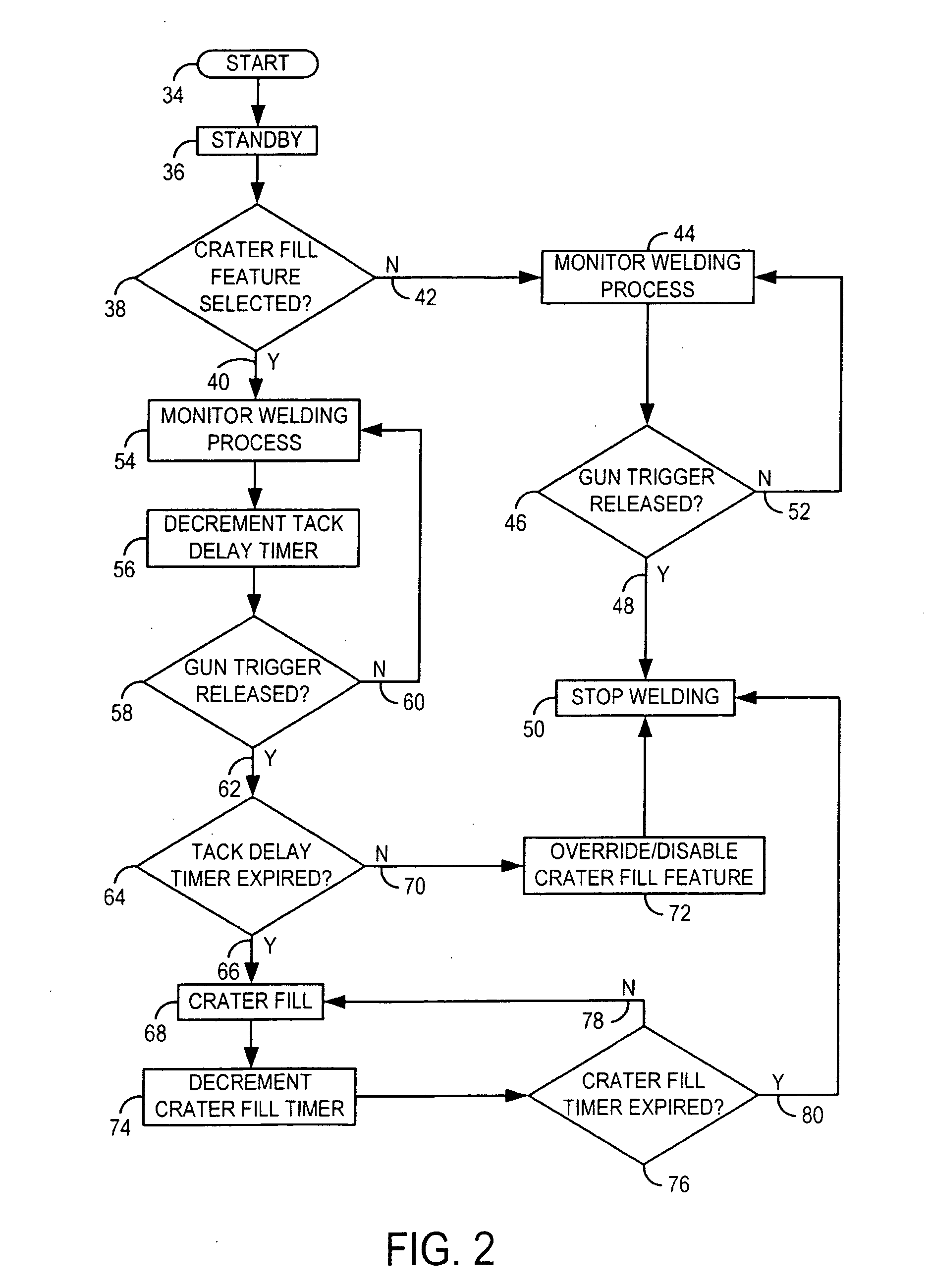
[0010] A controller for controlling operation of a welding-type system is presented and configured to automatically delineate between a tacking and a welding mode of operation. The controller is designed to decrement a timer at the onset of a weld event and if the timer expires before the weld event is complete, i.e. welding gun trigger remains depressed, then automatically enable a crater fill control feature of the welding-type system being used to support the welding event. On the other hand, if the timer has not expired when the weld event is terminated, then the controller automatically disables the crater fill control features and prevents the delivery of post-weld event filler to the weld or maintenance of a welding power at the weld sufficient to melt a consumable electrode.

Problems solved by technology

A drawback of carrying out tacking with a conventional welding machine is crater fill controls.
Absent the filler material, the end of the weld may prematurely fracture thereby causing damage to the weld and affect the integrity of the fusion.
Additionally, tacking is generally carried out in a relatively quick manner; however, crater filling adds time to the welding process.
Crater filling, however, adds to the amount of bonding metal between the workpieces which may hinder the separating of workpieces.
Requiring a user to manually activate or deactivate a crater fill control feature of a welding system can be particularly problematic.
This can be particularly time consuming if the tacking and welding is carried out relatively remotely from the welding system which is not uncommon in industrial applications.
Such a solution, however, can be particularly costly as it requires additional equipment and, moreover, an inefficient use of resources for those welding machines capable of operating at the high energy, low voltage current levels required for effective tacking.

Method used


Image

  • Method and system of welding with adaptive crater fill control
  • Method and system of welding with adaptive crater fill control
  • Method and system of welding with adaptive crater fill control

Examples


Embodiment Construction

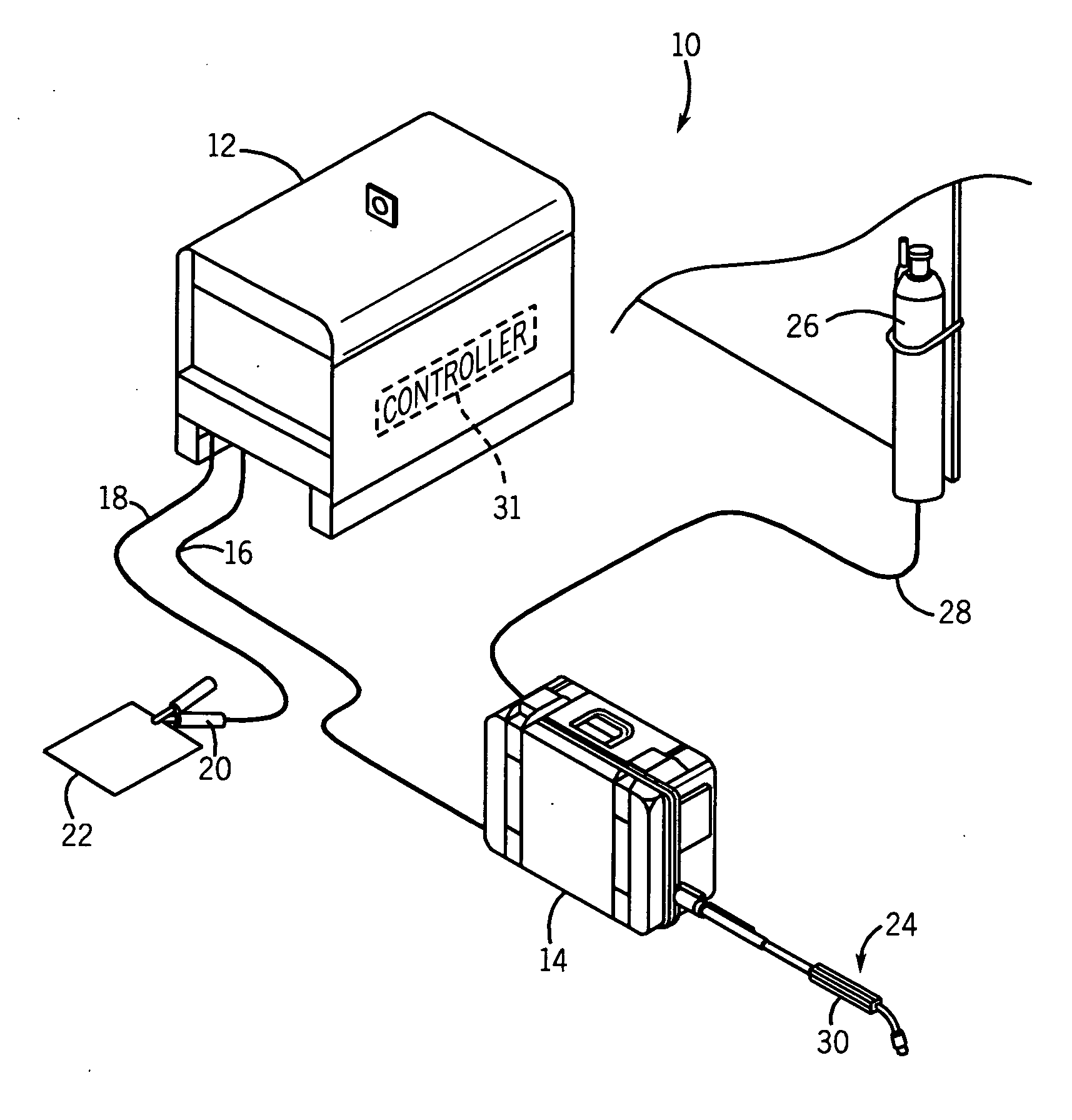
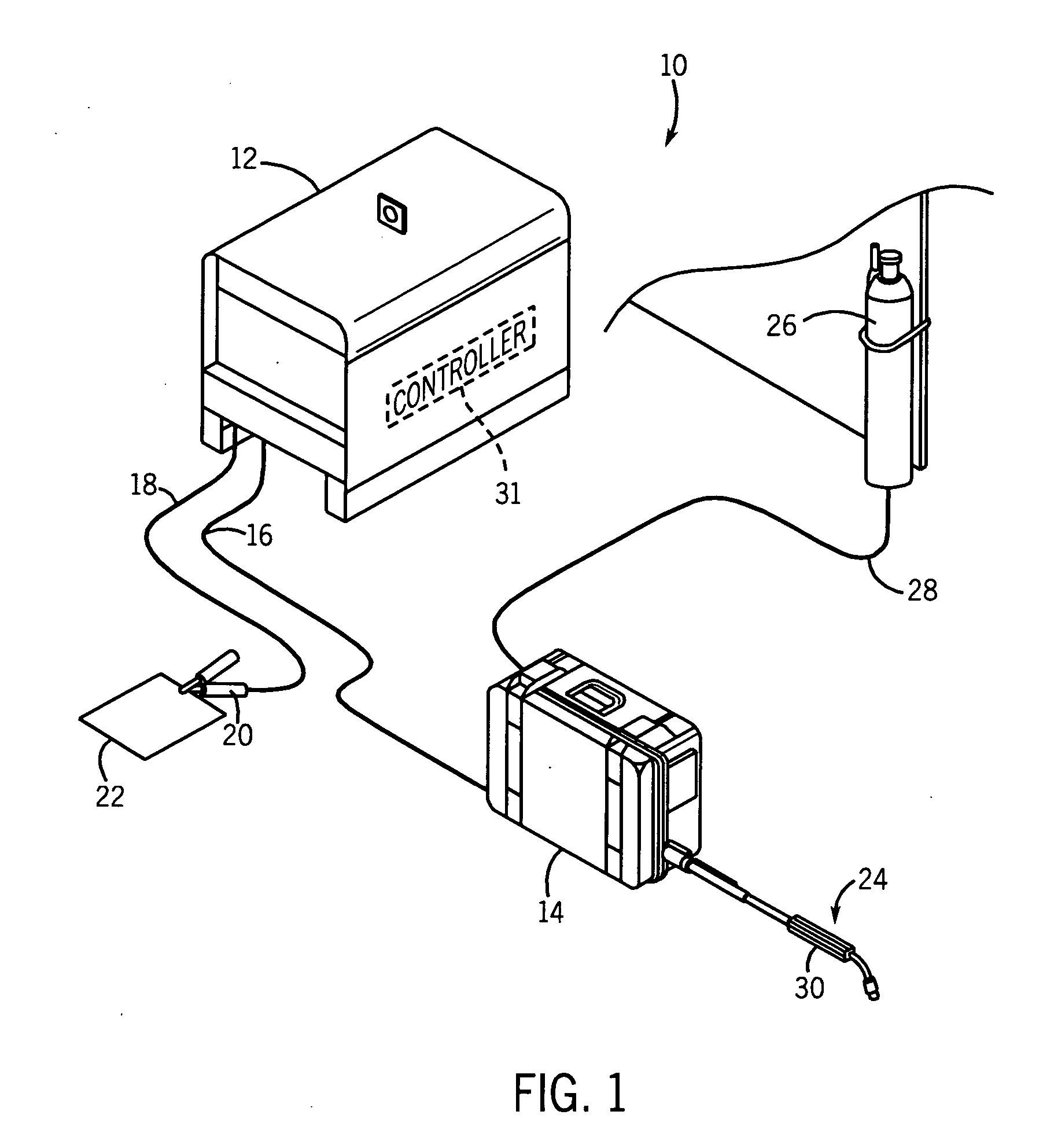
[0020] Referring to FIG. 1, a MIG welding system 10 includes a welding power source 12 designed to supply power to a wire feeder 14 through a weld cable 16. The power source is designed to run in one of a number of modes including constant voltage (CV) and constant current (CC). Also connected to the power source is a secondary work weld cable 18 that connects the power source to a clamp 20 designed to connect cable 18 to workpiece 22. Also connected to wire feeder 14 is a welding gun or torch 24 configured to supply consumable welding wire to a weld. Welding system 10 may further include a gas cylinder 26 connected to wire feeder 14 such that shielding gas can be provided through gas hose 28 for the MIG welding process. It is contemplated that the gas cylinder may be mounted to or in either power source 12 or wire feeder 14.

[0021] Power source 12 is designed to condition raw power supplied from a utility line or engine driven power supply and output power usable by the welding pro...


PUM

PropertyMeasurementUnit
temporal lengthaaaaaaaaaa
thresholdaaaaaaaaaa
energyaaaaaaaaaa

Abstract

The present invention is directed to a system and method of automatically adjusting the operating parameters of a welding-type system based on the type of welding being carried out. The invention includes a controller that is configured to automatically delineate between a tacking and a welding mode of operation. The controller is also designed to decrement a timer at the onset of a welding event and if the timer expires before the welding event is complete, then automatically enable a crater fill control feature of the welding-type system being used to support the weld event. If the timer has not expired when the weld event is terminated, then the controller automatically disables the crater fill control features and prevents the delivery of post-weld event termination filler to the weld or maintenance of a welding power at the weld sufficient to melt a consumable electrode.

Description

BACKGROUND OF THE INVENTION [0001] The present invention relates generally to crater fill controls for a welding-type process and, more particularly, to a method and system of adaptively activating an automatic crater fill feature of a welding-type system based on the type of welding-type operation being carried out. The present invention is particularly applicable with automatically delineating between a tacking mode of operation and a welding mode of operation. [0002] Tacking is a welding technique that is commonly used in light industrial applications for preliminarily fusing workpieces to one another such that the workpieces can be handled in a more manageable fashion when a final, complete weld is used to complete the fusing process. A “tack” is generally recognized as a light non-permanent weld between workpieces that can, if needed, be broken without damage to the workpieces. Tacking is often used in applications where a relatively precise alignment or orientation between wor...

Claims


Application Information

Patent Timeline
Patent Type & Authority Applications(United States)
IPC IPC(8): B23K9/10
CPCB23K9/0953B23K9/0956B23K9/1037B23K9/125
Inventor KAUFMAN, CHARLES L.SCHEELK, GARY L.
Owner ILLINOIS TOOL WORKS INC
Learn More