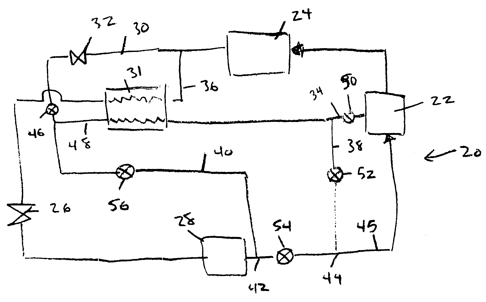
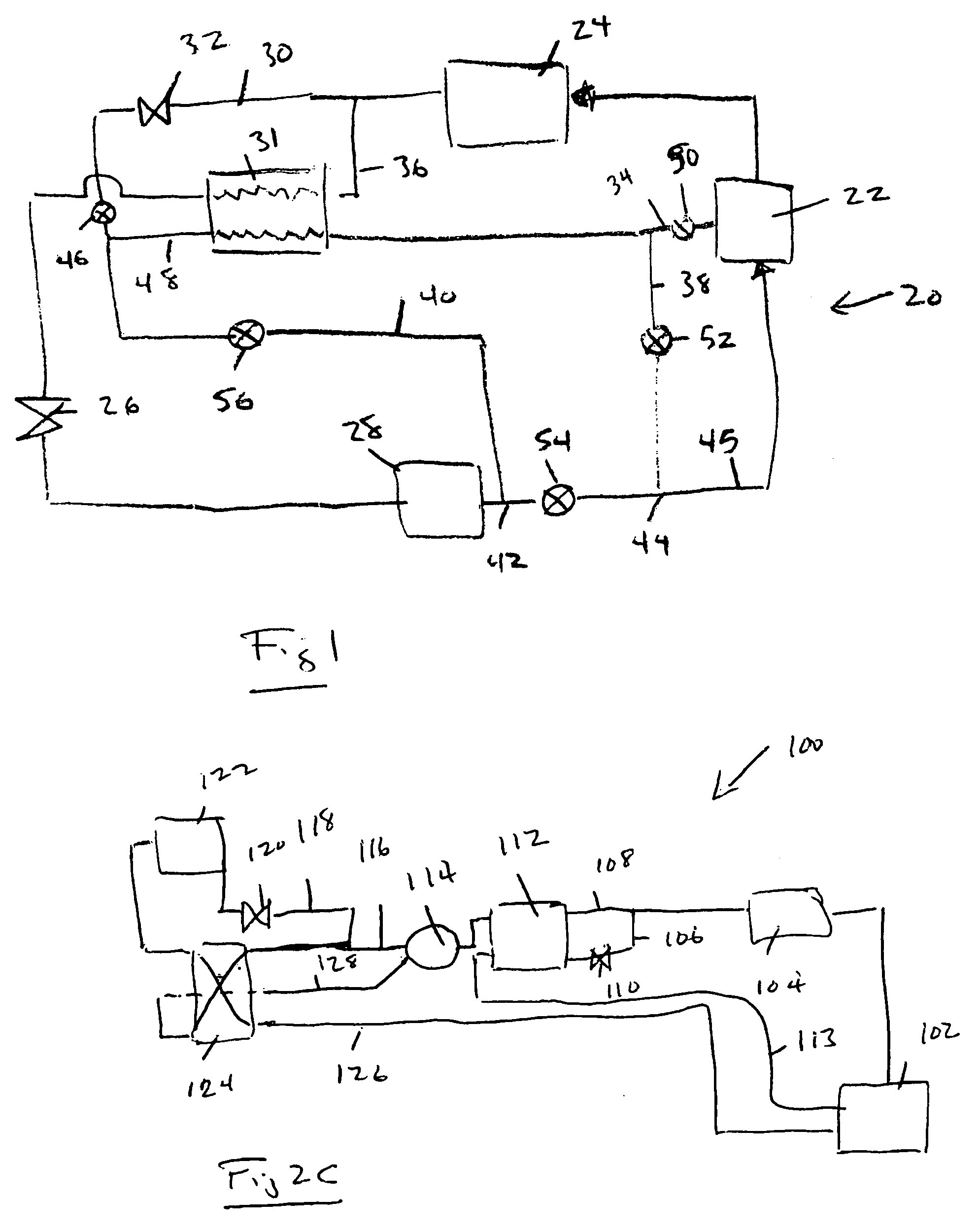
Refrigerant system with common economizer and liquid-suction heat exchanger
a technology of liquid-suction heat exchanger and refrigerant system, which is applied in the direction of refrigeration components, mechanical equipment, lighting and heating equipment, etc., can solve the problems of high cost and cumbersome provision of both options
- Summary
- Abstract
- Description
- Claims
- Application Information
AI Technical Summary
Benefits of technology
Problems solved by technology
Method used
Image
Examples
embodiment 60
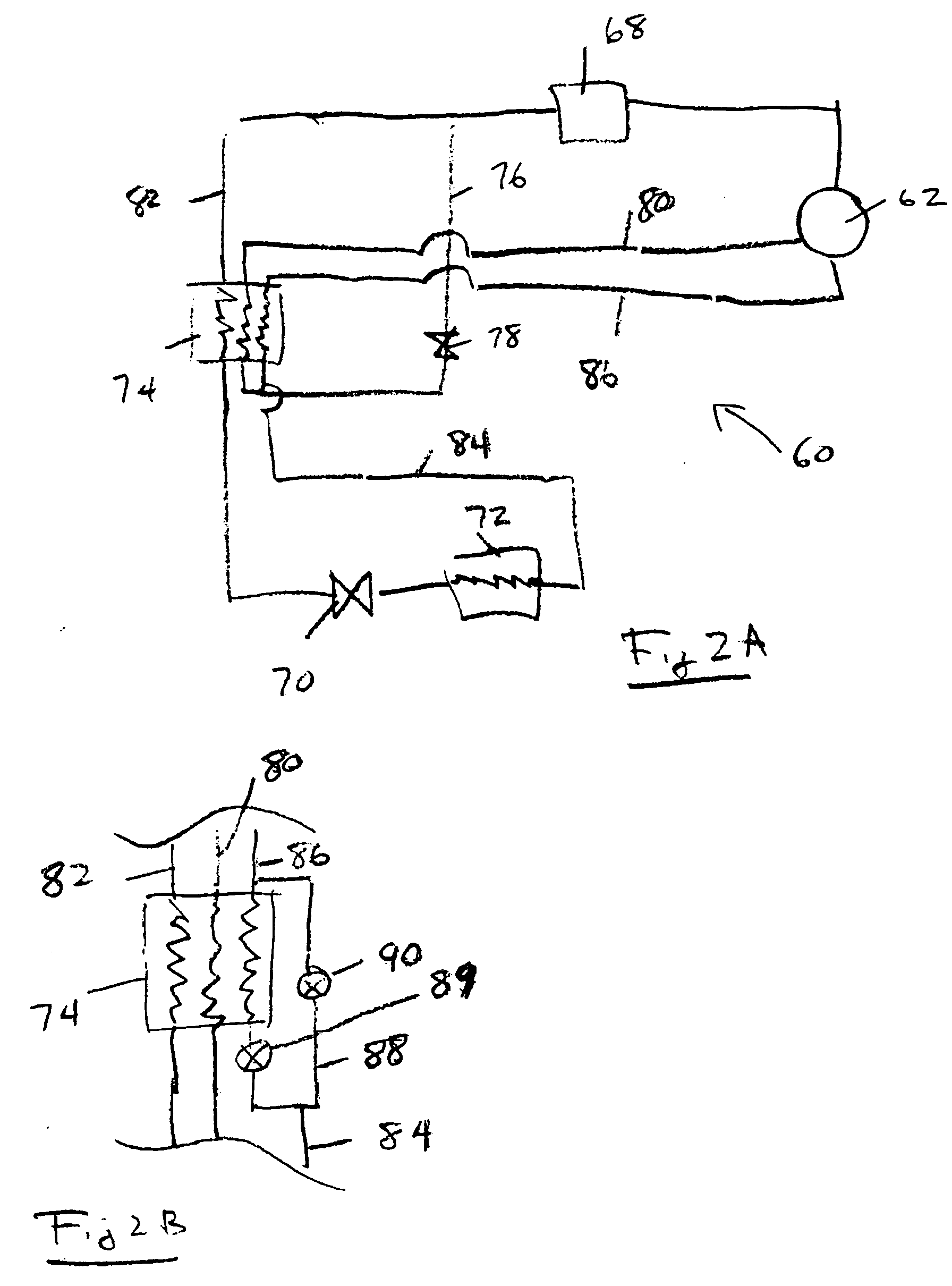
[0025]FIG. 2A shows another embodiment 60 with the economized compressor 62. Refrigerant downstream of the compressor 62 passes through a condenser 68, a main expansion device 70, and an evaporator 72. A common heat exchanger 74 receives refrigerant from an economizer circuit tap line 76 through an economizer expansion device 78. The tapped refrigerant would flow through an economizer circuit return line 80 back to the economizer port of the compressor 62 at some intermediate pressure. The main liquid refrigerant line 82 downstream of the condenser also passes through the common heat exchanger 74. A line 84 downstream of the evaporator 72 passes through the common heat exchanger 74 as well, and then back to a suction line 86 that returns refrigerant to the suction port of the compressor 62. This schematic selectively provides an economizer function by opening or closing the economizer expansion device 78. In case the economizer expansion device 78 is not equipped with a shutoff capa...
embodiment 100
[0027] Another embodiment 100 shown in FIG. 2C is a variation of the configuration presented in FIG. 2B. In this embodiment, an economizer function and a liquid-suction heat exchanger function are provided by separate units, 112 and 124 respectively, while a three-way valve 114 selectively routes the refrigerant through or around the liquid-suction heat exchanger 124.
[0028] An economized compressor 102 delivers refrigerant to a downstream condenser 104. A tap 106 from a main liquid refrigerant line 108 passes through an economizer expansion device 110, which is also utilized as a shut-off valve in this schematic. The refrigerant from both the tap 106 and main liquid refrigerant line 108 flows through the economizer heat exchanger 112. In fact, while the two are shown flowing in the same direction, in practice, it would be preferable if they were in a counter-flow relationship. If no economizer function is desired, then valve 110 is shut. The three-way valve 114 receives the refriger...
PUM
 Abstract
Description
Claims
Application Information
 - R&D
- Intellectual Property
- Life Sciences
- Materials
- Tech Scout
- Unparalleled Data Quality
- Higher Quality Content
- 60% Fewer Hallucinations
Browse by: Latest US Patents, China's latest patents, Technical Efficacy Thesaurus, Application Domain, Technology Topic, Popular Technical Reports.
© 2025 PatSnap. All rights reserved.Legal|Privacy policy|Modern Slavery Act Transparency Statement|Sitemap|About US| Contact US: help@patsnap.com


