
Vital sign-monitoring system with multiple optical modules

a sign-monitoring system and optical module technology, applied in the field of medical devices for monitoring pulse oximetry and blood pressure, can solve problems such as motion-related artifacts

Inactive Publication Date: 2006-06-08
BANET DR MATTHEW JOHN
View PDF98 Cites 160 Cited by
  • Summary
  • Abstract
  • Description
  • Claims
  • Application Information

AI Technical Summary

Benefits of technology

[0008] The present invention measures vital signs (e.g., blood pressure, pulse oximetry, and heart rate) from a patient using a body-worn device that features at least two optical modules. Each optical module typically features two light sources (red, infrared) and a photodetector. Both optical modules are configured to measure time-dependent signals describing the patient's flowing blood. A processor analyzes the time-dependent signals to determine the patient's vital signs. Once the vital signs are measured, a wireless transmitter in the body-worn device transmits them to an external device. Processing signals from least two optical modules compensates for motion-related artifacts and noise normally present in signals used to determine vital signs from a device featuring just a single optical module.

Problems solved by technology

This generates ‘noise’ in the plethysmograph, which in turn can lead to motion-related artifacts in data describing pulse oximetry and heart rate.

Method used


Image

  • Vital sign-monitoring system with multiple optical modules
  • Vital sign-monitoring system with multiple optical modules
  • Vital sign-monitoring system with multiple optical modules

Examples


Embodiment Construction

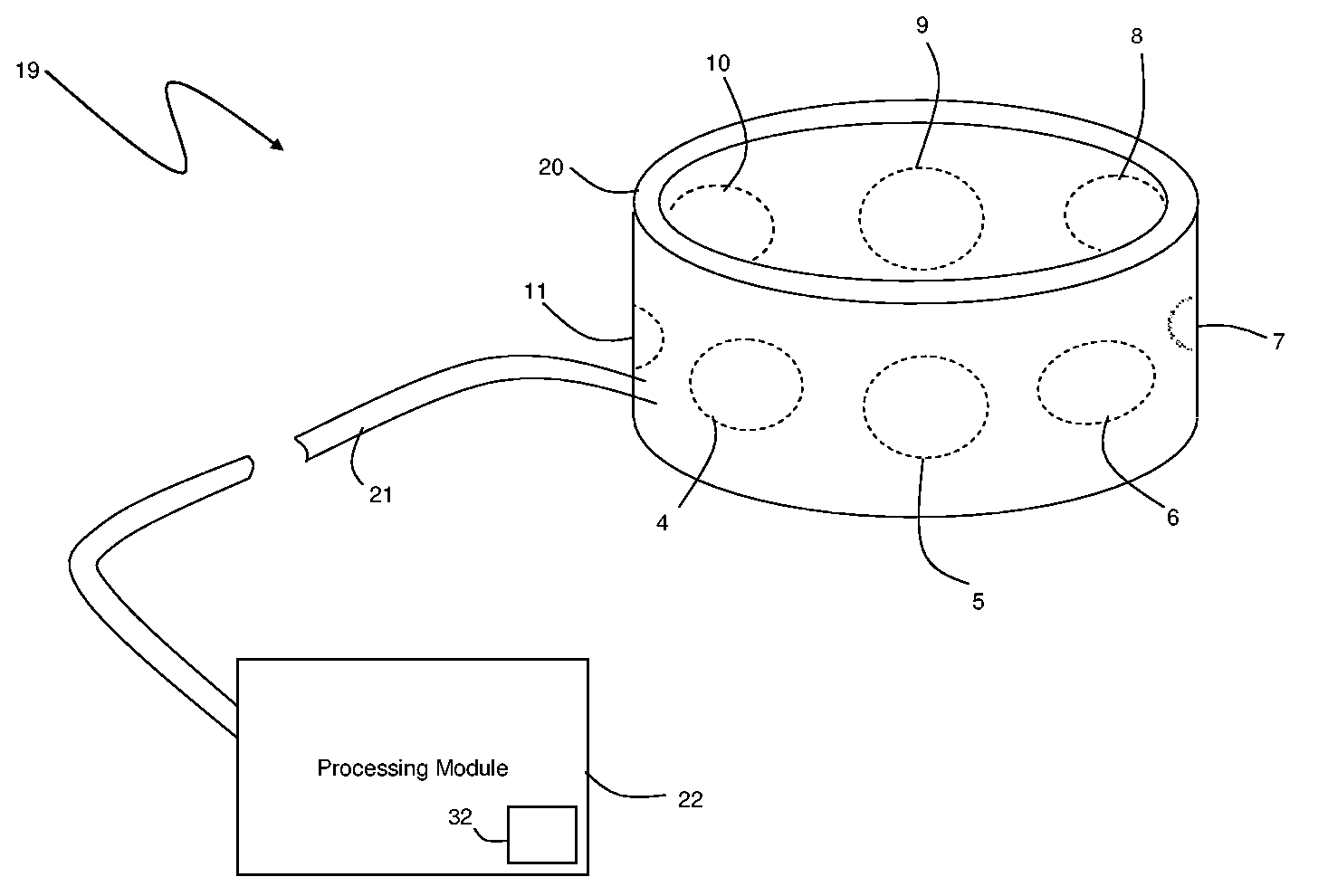
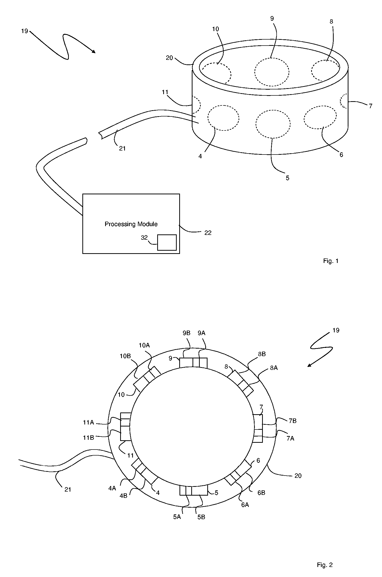
[0020]FIGS. 1 and 2 show a medical device 19 according to the invention that features an annular optical ring module 20 that includes multiple optical modules 4-11, each of which measures a plethysmograph from a patient. The optical modules 4-11 are evenly disposed around a perimeter of the ring module 20 and each feature a photodetector 4B-11B that detects radiation, and a pair of LEDs 4A-11A that generate red and infrared radiation. An electrical cable 21 connects the optical modules 4-11 to a processing module 22. When a patient wears the ring module 20 on a finger, each optical module 4-11 simultaneously measures a signal describing the flow of blood in an underlying artery. The signal from each optical module 4-11 passes through the cable 21 to the processing module 22, which includes a microprocessor 32 that processes the signals to determine an individual plethysmograph for each optical module 4-11. An algorithm running on the microprocessor 32 then analyzes the plethysmograp...


PUM


Abstract

The invention features a medical device that measures vital signs (e.g., blood pressure, pulse oximetry, and heart rate) from a patient using at least two optical modules. Each optical module typically features two light sources (red, infrared) and a photodetector. Both optical modules are configured to measure time-dependent signals describing the patient's flowing blood. A processor analyzes the time-dependent signals to determine the patient's vital signs. Once the vital signs are measured, a wireless transmitter in the body-worn device transmits them to an external device. Processing signals from least two optical modules compensates for motion-related artifacts and noise normally present in signals used to determine vital signs from a device featuring just a single optical module.

Description

CROSS REFERENCES TO RELATED APPLICATION [0001] Not Applicable STATEMENT REGARDING FEDERALLY SPONSORED RESEARCH OR DEVELOPMENT [0002] Not Applicable BACKGROUND OF THE INVENTION [0003] 1. Field of the Invention [0004] The present invention relates to medical devices for monitoring pulse oximetry and blood pressure. [0005] 2. Description of the Related Art [0006] Pulse oximeters are medical devices featuring an optical module, typically worn on a patient's finger or ear lobe, and a processing module that analyzes data generated by the optical module. The optical module typically features first and second light sources (e.g., light-emitting diodes, or LEDs) that transmit optical radiation at, respectively, red (λ˜630 nm) and infrared (λ˜900 nm) wavelengths. The optical module also features a photodetector that detects radiation transmitted or reflected by an underlying artery. Typically the red and infrared LEDs sequentially emit radiation that is partially absorbed by flowing blood in ...

Claims


Application Information

Patent Timeline
IPC IPC(8): A61B5/02A61B5/00
CPCA61B5/0205A61B5/021A61B5/02438A61B5/14552A61B5/6814A61B5/6816A61B5/6826A61B5/6838A61B5/002
Inventor BANET, MATTHEW JOHNMORRIS, BRETT GEORGEVISSER, HENK
Owner BANET DR MATTHEW JOHN
Learn More