
Magnetofluiddynamic pumps for non-conductive fluids

a magnetofluid and fluid technology, applied in the field of magnetofluiddynamic pumps, can solve the problems of affecting the performance of the device, generating a lot of heat during operation, and temperature buildup in the device,

Inactive Publication Date: 2006-06-08
NANOCOOLERS
View PDF26 Cites 4 Cited by
  • Summary
  • Abstract
  • Description
  • Claims
  • Application Information

AI Technical Summary

Benefits of technology

[0011] Various embodiments of magnetofluiddynamic (MFD) pumps and pumping systems are disclosed herein. An MFD pump according to at least one embodiment of the invention employs a piston that is at least partially made up of one or more fluids. In some embodiments, the piston is a completely (or almost completely) liquid piston made up of one or more liquid metals, liquid metal alloys, or some combination of other conductive liquids. In some embodiments, the piston includes a rod, plug, disk, ball, or other mass of conductive material at least partially surrounded by a conductive liquid. In some embodiments, the piston includes a conductive slurry, or some similar combination of solids and liquids that permits the piston to be driven using a magnetic field in conjunction with an electric current passing through the piston.
[0012] Various embodiments of an MFD pump according to the present invention include a working fluid passage having multiple valve-delimited chambers coupled between an input and an output of the workin

Problems solved by technology

Electronic devices such as central processing units, graphic-processing units and laser diodes as well as electrical devices, such as transformers, generate a lot of heat during operation.
If generated heat is not dissipated properly from high power density devices, this may lead to temperature buildup in these devices.
The buildup of temperature can adversely affect the performance of these devices.
For example, excessive temperature buildup may lead to malfunctioning or breakdown of the devices.
For example, in portable systems such as laptops and notebooks, the high volume and weight of liquid metals is a restriction on their use as coolants.
Moreover, in case of cooling of high voltage power supplies and transformers, the use of electrically conductive liquid metals may not be recommended.
However, this system suffers from certain disadvantages.
Firstly, the movement of the two liquid metal pistons has to be synchronized for proper functioning.
Secondly, the system produces discontinuous outflow of the fluid since the outflow is restricted to half the oscillatory cycle of the pistons (in one particular embodiment, fluid is pumped out only when the valving piston moves to the left and the pumping piston moves up, and not in the reverse movement).
Thirdly, the valve action is based on the surface tension properties of liquid metals resulting in poor pressure heads and poor mean time between failures (MTBF).

Method used


Image

  • Magnetofluiddynamic pumps for non-conductive fluids
  • Magnetofluiddynamic pumps for non-conductive fluids
  • Magnetofluiddynamic pumps for non-conductive fluids

Examples


second embodiment

[0031] Referring now primarily to FIG. 3, the structure of a pump in accordance with an embodiment of the present invention will hereinafter be described. The pump in accordance with the second embodiment comprises a suction and pumping assembly 300 for sucking and pumping the working fluid, an inlet conduit 302 for allowing the inflow of the working fluid, an outlet conduit 304 for allowing the outflow of the working fluid and a valve 306 in inlet conduit 302 and a valve 307 in outlet conduit 304.

[0032] Suction and pumping assembly 300 comprises three hollow chambers—a first vertical chamber 308, a second vertical chamber 310 and an intermediate horizontal chamber 312. First vertical chamber 308 is partially filled and second vertical chamber 310 is completely filled with a liquid metal 314. Intermediate horizontal chamber 312 is completely filled with liquid metal 314. Liquid metal 314 is driven in an oscillatory manner by an AC-powered reciprocating MFD pump 316 connected to inte...

first embodiment

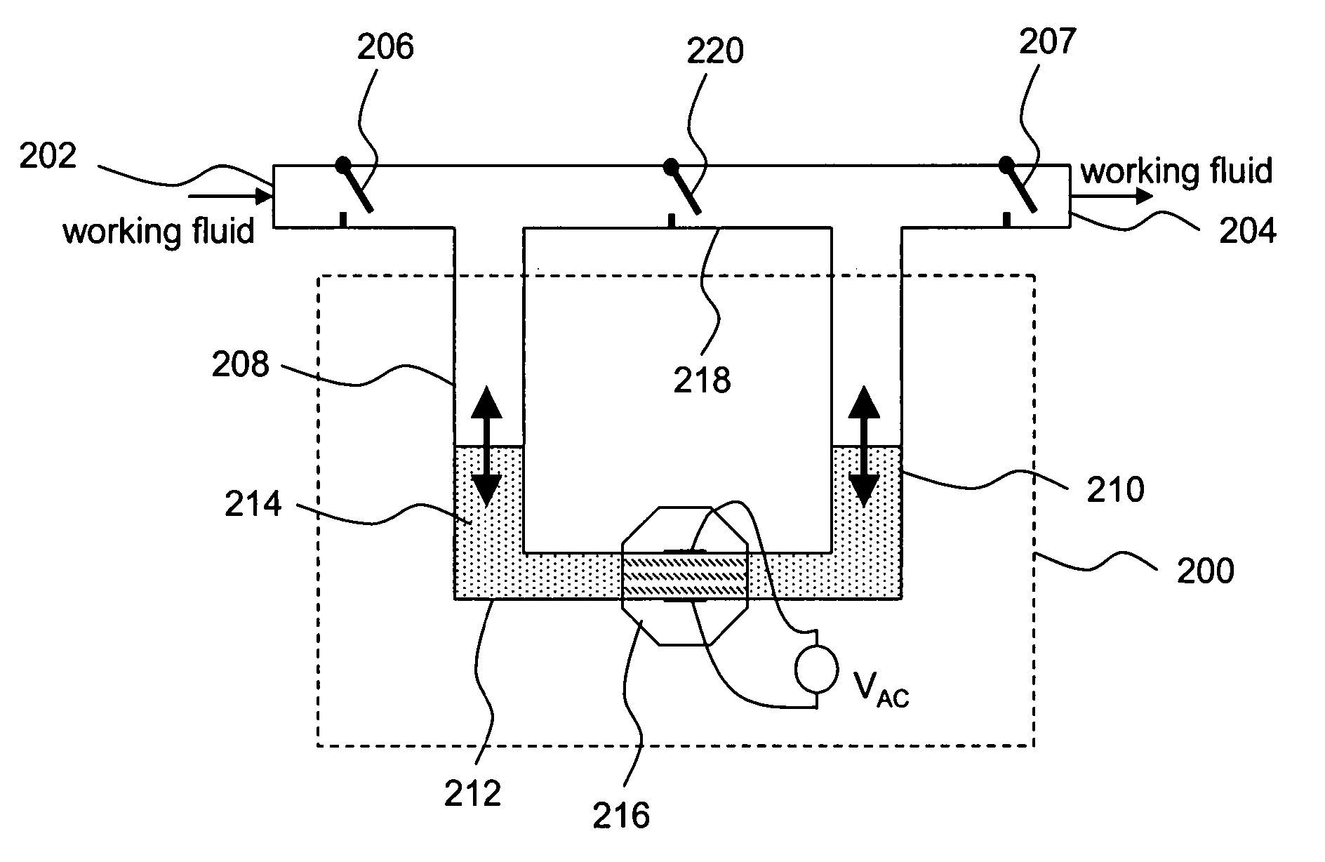
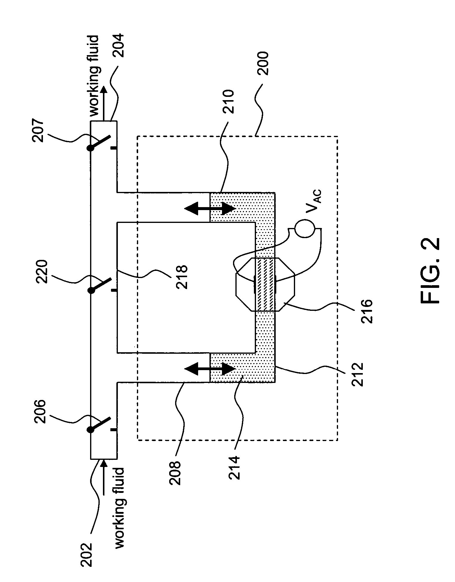
[0045] In some embodiments of the present invention, suction and pumping assemblies, in accordance with any of the previously discussed embodiments, are combined in parallel. Such a structure results in an increase in the pumping capacity and pressure head. This results in an increase in the power of the pump. Referring now primarily to FIG. 5, an exemplary structure of one such pump will hereinafter be described. Suction and pumping assemblies 5001 to 500M, corresponding to the pump (shown in FIG. 2), are combined in parallel. The working fluid flows into suction and pumping assemblies 5001 to 500M through an inlet conduit 502 and is pumped out through an outlet conduit 504.

[0046] The operating voltage of the pump provided by this embodiment is proportional to the number of suction and pumping assemblies connected in parallel. This provides flexibility for increasing the operating voltage of the pump. Higher operating voltage may be desirable in some cases due to the following reas...


PUM


Abstract

A magnetofluiddynamic (MFD) pump including a liquid (or partially liquid) piston and at least two valve-delimited chambers is disclosed. The valve-delimited chambers may be coupled, in series or parallel, between the input and the output of a fluid passage to provide either intermittent flow of the working fluid or substantially continuous working fluid flow. In at least one embodiment, a piston chamber housing a conductive liquid (e.g. liquid) piston is coupled to two valve-delimited chambers so that a single stroke of the piston both draws working fluid into one of the chambers and pushes working fluid out of the other chamber.

Description

CROSS-REFERENCE TO RELATED APPLICATION(S) [0001] This application is a continuation of commonly-owned, co-pending international application PCT / US04 / 16018, filed 21 May 2004. This application is also a continuation-in-part of commonly-owned, co-pending U.S. application Ser. No. 10 / 443,186, filed 22 May 2003.BACKGROUND [0002] 1. Field of the Invention [0003] The present invention relates to applications of magnetofluiddynamic (MFD) pumps. More particularly, it relates to the use of MFD pumps for pumping of non-conductive (e.g., dielectric) fluids. [0004] 2. Description of the Related Art [0005] Electronic devices such as central processing units, graphic-processing units and laser diodes as well as electrical devices, such as transformers, generate a lot of heat during operation. If generated heat is not dissipated properly from high power density devices, this may lead to temperature buildup in these devices. The buildup of temperature can adversely affect the performance of these d...

Claims


Application Information

Patent Timeline
IPC IPC(8): F04B37/02H02K44/00F04B17/04F04B19/00F04B53/14F04F1/06
CPCF04B17/044F04B19/006F04B53/141F04F1/06
Inventor GHOSHAL, UTTAMMINER, ANDREW CARLKOLLE, KEY
Owner NANOCOOLERS
Learn More