Tire size reduction/wire separation system

a technology of wire separation and reduction, which is applied in the direction of solid separation, cocoa, sorting, etc., to achieve the effects of low manufacturing cost, convenient and efficient manufacturing and marketing, and durable and reliable construction

Active Publication Date: 2006-06-08
IND SHREDDERS LLC
View PDF5 Cites 26 Cited by
  • Summary
  • Abstract
  • Description
  • Claims
  • Application Information

AI Technical Summary

Benefits of technology

[0020] It is, therefore, an object of the present invention to provide a new and improved tire size reduction / wire separation system which has all of the advantages of the prior art tire reduction and separation system which may be easily and efficiently manufactured and marketed.
[0021] It is further object of the present invention to provide a new and improved tire reduction and separation system which is of durable and reliable construction.
[0022] An even further object of the present invention is to provide a new and improved tire reduction and separation system which is susceptible of a low cost of manufacture with regard to both materials and labor, and which accordingly is then susceptible of low prices of sale to the consuming public, thereby making such tire reduction and separation system economically available to the buying public.
[0023] Even still another object of the present invention is to provide a tire reduction and separation system for safe and efficient tire size reduction and / or wire separation of scrap tire material, cable and wire along with other materials that have properties that are commingled which need to be separated for means of recycling and recovery.

Problems solved by technology

While these devices fulfill their respective, particular objectives and requirements, the aforementioned patents do not describe a tire size reduction / wire separation system that allows safe and efficient tire size reduction and / or wire separation of scrap tire material, cable and wire along with other materials that have properties that are commingled which need to be separated for means of recycling and recovery.

Method used


Image

  • Tire size reduction/wire separation system
  • Tire size reduction/wire separation system
  • Tire size reduction/wire separation system

Examples


Embodiment Construction

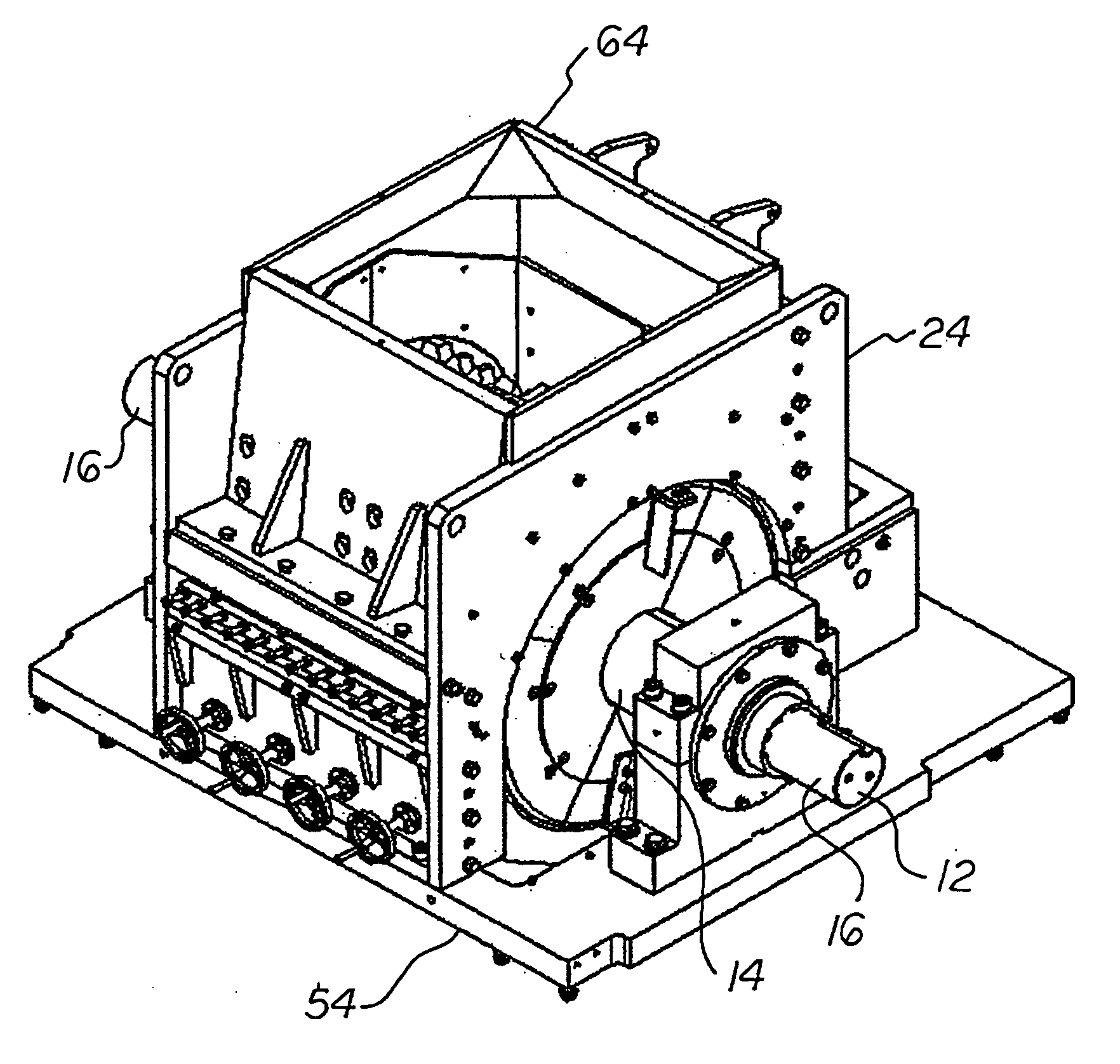
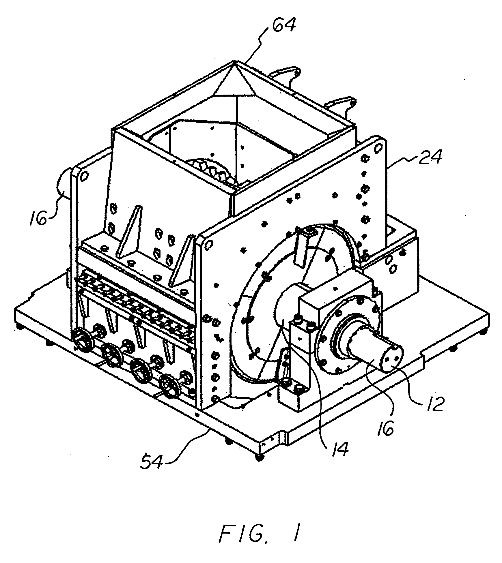
[0037] With reference now to the drawings, and in particular to FIG. 1 thereof, the preferred embodiment of the new and improved tire size reduction / wire separation system embodying the principles and concepts of the present invention will be described.

[0038] The present invention, the tire size reduction / wire separation system, is comprised of a plurality of components. Such components in their broadest context include a drive shaft, rotors with knives and an independent housing with central, upper and lower sections. Such components are individually configured and correlated with respect to each other so as to attain the desired objectives. The components form a tire size reduction / wire separation system for the safe and efficient size reduction and wire separation of scrap tire material, cable and wire along with other materials that have properties that are commingled which need to be separated for means of recycling and recovery.

[0039] The first component of the system is a d...


PUM


Abstract

A tire size reduction / wire separation system comprising a drive shaft; a plurality of rotors mounted on the drive shaft, each rotor having axial slots with a rotatable knife removably secured within each slot; and an independent housing supporting the drive shaft and rotors. The independent housing has a central region with stationary knives. The roots and crests of the stationary knives are matingly oriented and respect to the roots and crests of the rotatable knives. The independent housing also has lateral regions including an annual wear ring vertically secured to the axial ends of the rotors. Each lateral region also includes a wear liner with a circular opening with a diameter greater than the exterior diameter of the wear rings.

Description

BACKGROUND OF INVENTION [0001] 1. Field of the Invention [0002] The present invention relates to a tire size reduction / wire separation system and more particularly pertains to the safe and efficient tire size reduction and / or wire separation of scrap tire material, cable and wire along with other materials that have properties that are commingled which need to be separated for means of recycling and recovery. [0003] 2. Description of the Prior Art [0004] The use of tire reduction and separation devices of known designs and configurations is known in the prior art. More specifically, the reduction and separation devices of known designs and configurations previously devised and utilized are known to consist basically of familiar, expected, and obvious structural configurations, notwithstanding the myriad of designs encompassed by the crowded prior art, which has been developed for the fulfillment of countless objective and requirements. [0005] By way of example, U.S. Pat. No. 3,214,1...

Claims


Application Information

Patent Timeline
Patent Type & Authority Applications(United States)
IPC IPC(8): B02C18/16
CPCB02C18/141B02C18/146B02C18/18B02C23/08B02C2018/162B02C2023/165B02C2201/04B02C18/14B02C18/184B02C18/24B02C13/02B02C13/28B02C13/284
Inventor ASTAFAN, CHARLES G.STUHLMILLER, DAVID A.MOORE, PETER M.
Owner IND SHREDDERS LLC
Why Eureka
Try Eureka