Pressure indicator

Inactive Publication Date: 2006-06-08
DANFOSS AS
View PDF7 Cites 2 Cited by
  • Summary
  • Abstract
  • Description
  • Claims
  • Application Information

AI Technical Summary

Benefits of technology

[0004] It is an object of a preferred embodiment of the present invention to provide a pressure indicator which is simple to produce even with small outer dimensions and which can be more easily read even in low pressure applications. Accordingly, the present invention, in a first aspect, provides a pressure indicator of the kind mentioned in the introduction characterised in that the indicator further comprises a flexible third wall part separating the pressure chamber from a second chamber, the second chamber holding a pressure P2.
[0005] Due to the flexibility of the third wall part, increased sensitivity of the indicator can be obtained and it is therefore possible to read the indicator more clearly even in low pressure applications.
[0006] To increase simplicity in the reading of the indicator, one of the first, second or third wall parts could be made from a transparent material and the fluid could be optically detectable, e.g. coloured in an easily detectable colour such as red, blue, black etc. In this context, the wording “optically detectable” denotes a fluid which is detectable by its absorption and / or reflection of electromagnetic radiation in any wave length, e.g. a fluid which can be detected via X-ray, infra-red or visually in visible light. Since the deflection of the flexible wall parts causes a displacement of the optically detectable fluid, a pressure difference between the fluid medium and the reference pressure is detectable by observing the transparent wall part to detect e.g. the colour intensity, or an infrared or X-ray absorption. “Transparent” denotes that electromagnetic radiation of a specified wavelength can penetrate relatively freely. As an example, the fluid could be coloured to be visually detectable merely by looking at a transparent wall part, e.g. a wall part made of glass. In one embodiment, the first wall part could comprise a stiff plate element, e.g. made from a transparent material such as glass. The second and third wall parts could comprise a very thin and flexible membrane made from silicon or rubber to deflect upon even very small pressure differences.

Problems solved by technology

Depending on the need for accuracy and reliability, all elements are machined within narrow tolerances and, accordingly, the cost for making traditional pressure sensors is high, not least for making very small sensors, e.g. for medical applications.
Moreover, due to the mechanically moving elements, the reliability of traditional sensors may easily be influenced by external conditions such as changing temperatures or rough handling.
Indicators of the disclosed kind are in general not suitable for determining low pressure differences, and often, it is difficult to read the visual display diaphragm.

Method used


Image

  • Pressure indicator
  • Pressure indicator
  • Pressure indicator

Examples


Embodiment Construction

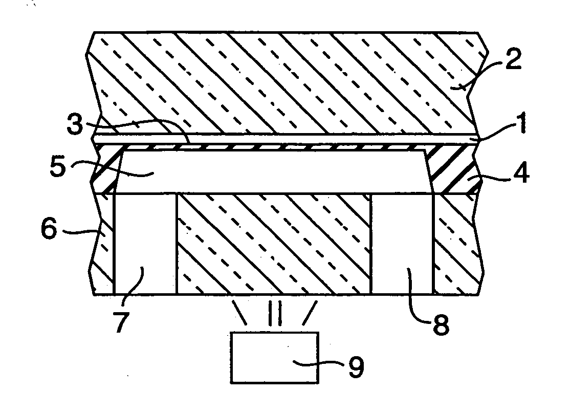
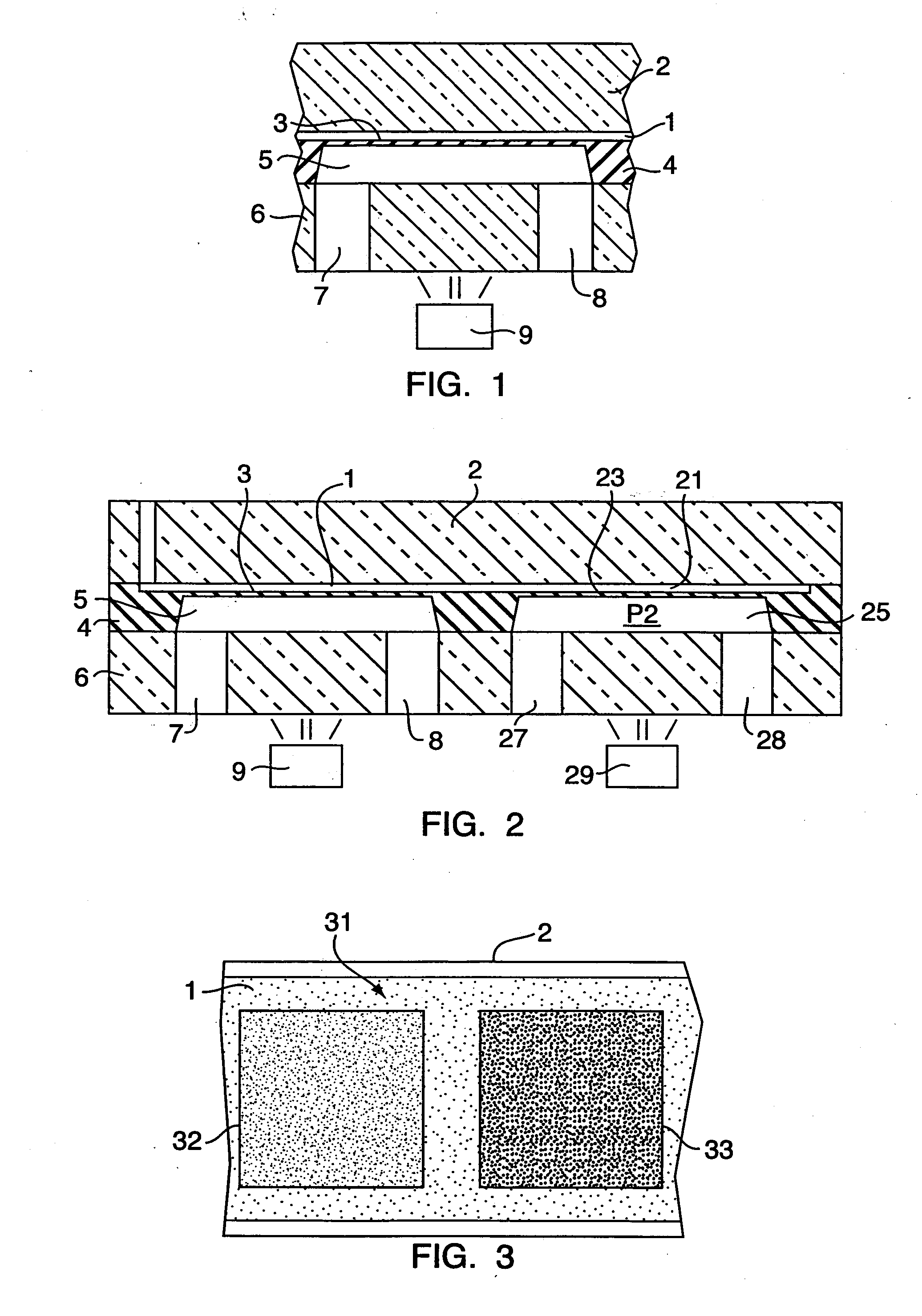
[0034] Referring to FIG. 1, the pressure indicator for detecting a pressure difference between a fluid medium and a reference pressure comprises a pressure chamber 1 having a first wall part 2 and a second wall part 3. The first wall part is transparent and could be made from a glass plate. The second wall part 3 is a flexible membrane formed by etching a part of a silicon plate 4 away. A first chamber 5 is separated from the pressure chamber via the flexible second wall part 3. Via the inflow and outflow channels 7, 8, the first chamber is in fluid communication with the fluid medium in question. The channels are formed in the plate 6, e.g. by drilling. Due to the arrangement of the flexible membrane between the pressure chamber and the first chamber, the membrane can be deflected either inwardly into the pressure chamber or outwardly out from the pressure chamber by a pressure difference between the internal pressure of the pressure chamber and the external pressure of the fluid m...


PUM


Abstract

The invention provides an indicator for indicating a pressure difference. The indicator has a reference pressure chamber with two flexible wall parts being influenced to deflect upon pressures P1 and P2. The deflection of the wall parts changes a distance between each of the wall parts and an inflexible wall part of the chamber and by inspecting the difference, a pressure difference between P1 and P2 can be determined. To enable visual inspection, the chamber can be filled with an optically detectable fluid and one of the wall parts could be transparent to allow visual reading by determining a colour of the fluid layer below the transparent part.

Description

CROSS REFERENCE TO RELATED APPLICATIONS [0001] This application is entitled to the benefit of and incorporates by reference essential subject matter disclosed in International Patent Application No. PCT / DK2004 / 000374 filed on May 28, 2004 and Danish Patent Application No. PA 2003 00817 filed Jun. 2, 2003.FIELD OF THE INVENTION [0002] The present invention relates to a simple and reliable indicator which can be produced cheaply in very small sizes for an optical indication of a pressure difference. In particular, the invention relates to a pressure indicator for indicating a pressure difference between a pressure P1 of a first chamber and a reference pressure. BACKGROUND OF THE INVENTION [0003] Pressure is typically indicated as a relative measure using standard units, e.g. bar, psi etc. In some applications, pressure sensors are inserted in a number of feed-lines to indicate a flow direction of a fluid medium. Often, such applications require no exact measure but merely an indicatio...

Claims


Application Information

Patent Timeline
IPC IPC(8): G01L19/12G01L19/08G01P13/00
CPCG01L19/08
Inventor RASMUSSEN, PER
Owner DANFOSS AS
Why Eureka
Try Eureka