Improvements in replication and related methods and devices, in particular for minimizing asymmetric form errors

Active Publication Date: 2020-11-12
HEPTAGON MICRO OPTICS
View PDF0 Cites 0 Cited by
  • Summary
  • Abstract
  • Description
  • Claims
  • Application Information

AI Technical Summary

Benefits of technology

The patent text discusses a method for reducing errors in the replication of surfaces. The method involves adding features to the replication tool that reduce the deviation of the replicated surfaces from the desired shape. This results in a more symmetrical form.

Problems solved by technology

Some types of form errors of replicated devices are of particular relevance, because they are hard to compensate.
Randomly occurring form errors are hard to handle.
But, depending on the circumstances and on the reproducibility, even such a (seemingly) simple form error can be difficult to handle.
Other form errors, however, can be still more difficult to handle, namely, e.g., form errors which are asymmetric.
Such asymmetric form errors cannot be overcome by identically scaling the replication tool along all directions.
Different scaling factors would have to be applied along different directions, which can be a cumbersome to implement.
Therefore, avoiding such deformations of the produced devices can be difficult to accomplish.
If, for example, the devices to be produced by replication using the replication tool shall exhibit surfaces of rotational symmetry, but the devices obtained are not of rotational symmetry but elliptical or deformed in a still more complicated way, a correction of the errors by adjusting the replication tool can be difficult, in particular if the replication tool itself shall be produced in a replication process using a master.
A master for the adjusted replication tool would have to exhibit a not rotational, but, e.g., an elliptical, symmetry, which can be more difficult than to produce a master having rotational symmetry.

Method used


Image

  • Improvements in replication and related methods and devices, in particular for minimizing asymmetric form errors
  • Improvements in replication and related methods and devices, in particular for minimizing asymmetric form errors
  • Improvements in replication and related methods and devices, in particular for minimizing asymmetric form errors

Examples


Embodiment Construction

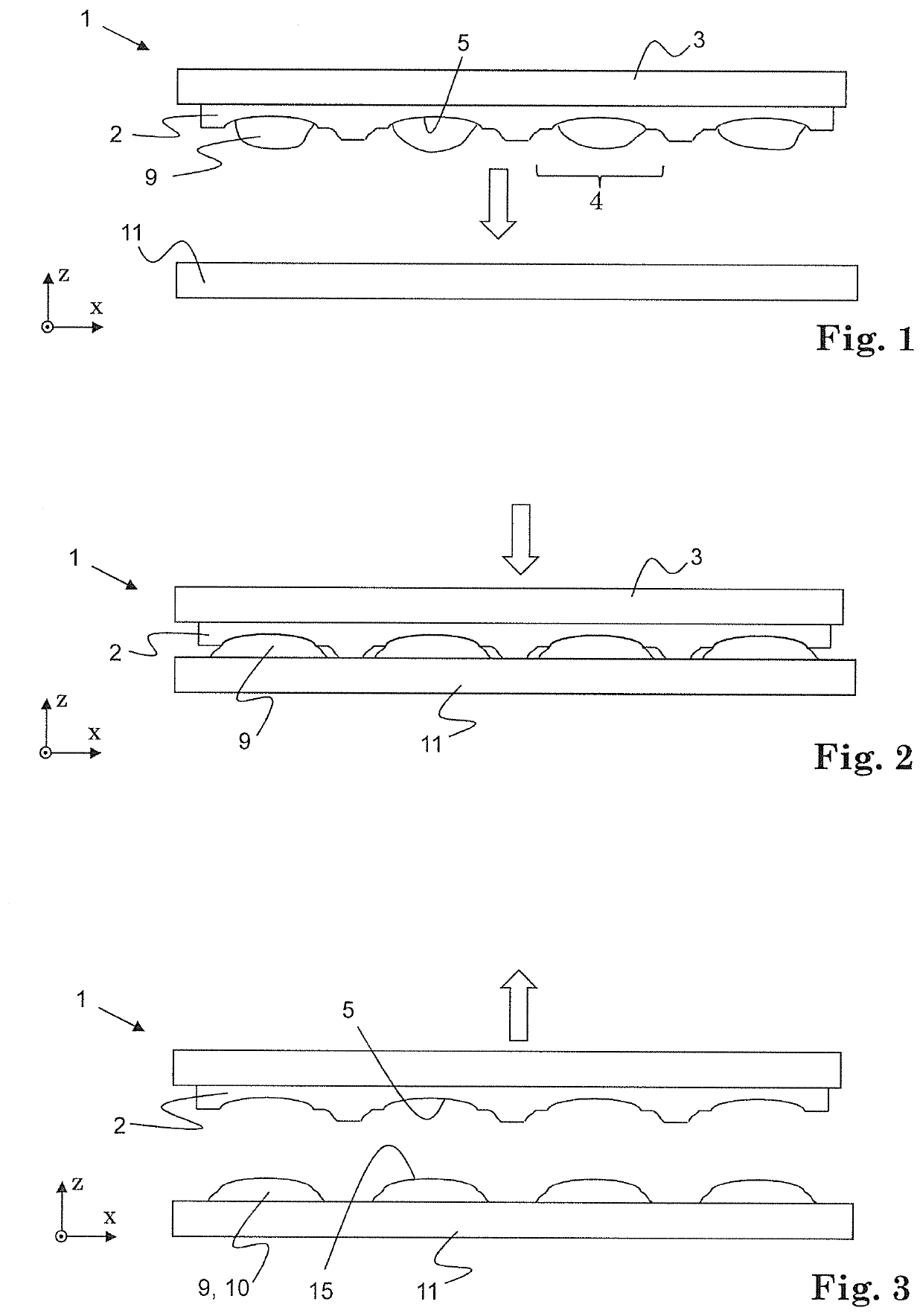
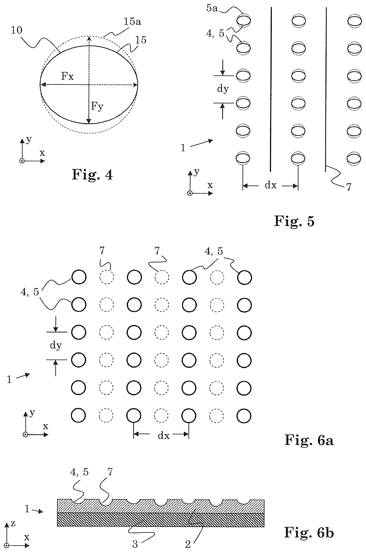
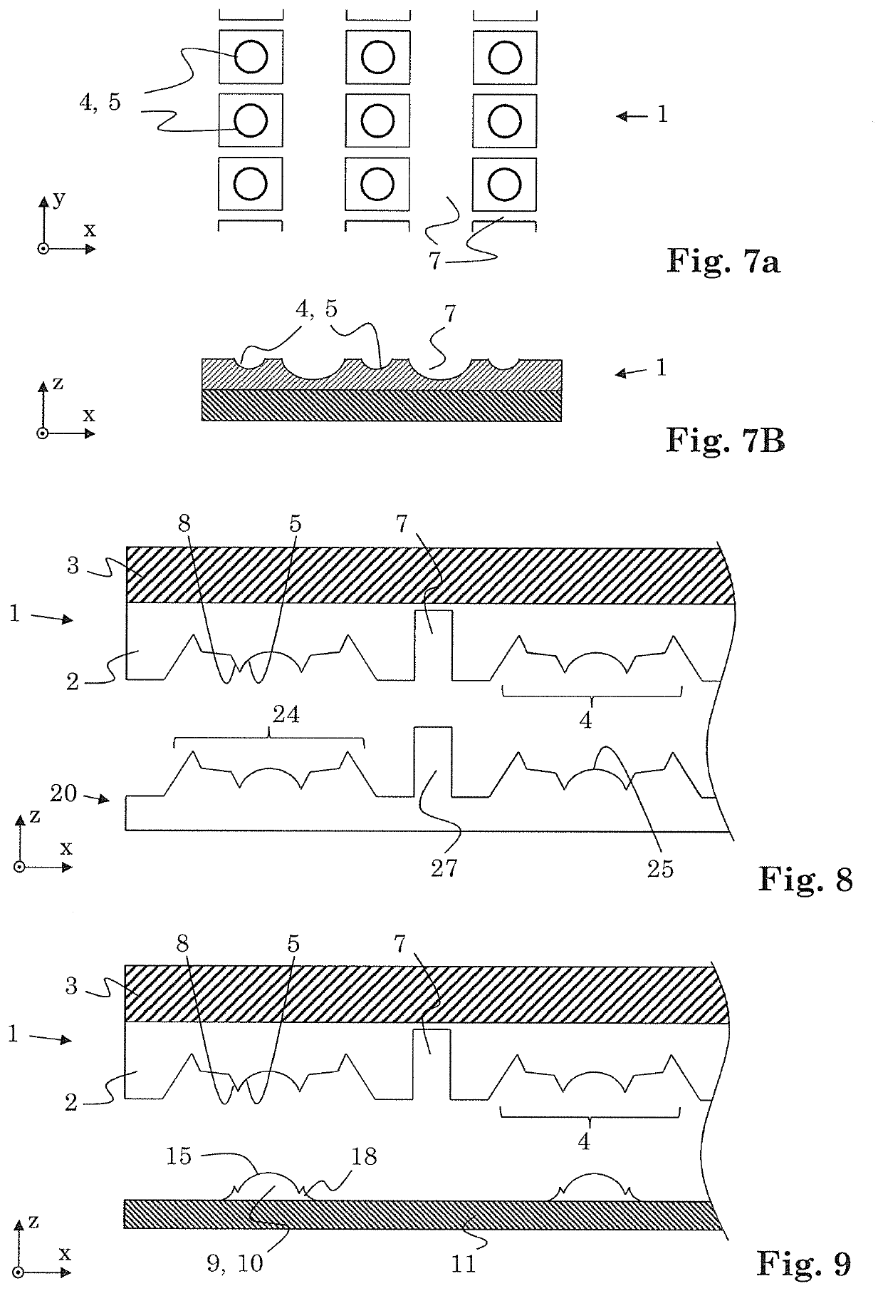
[0169]FIG. 1 schematically illustrates a replication tool 1 in a cross-sectional view which is a wafer-level replication tool for embossing. It includes a tool material 2 which adheres to a rigid carrier 3 such as a glass plate. The tool material 2 establishes a number of replication sites 4, four of which are illustrated in FIG. 1. In each replication site, a replication surface 5 is provided which exhibits the negative of the shape of a surface of a device to be produced by replication using the replication tool 1.

[0170]Replication tool 1 includes mutually distanced replication sites 4, for the manufacture of separate devices by replication, such as a multitude of microlenses.

[0171]The tool material 2 can be a resilient material, and it can be a material which is interspersed pores and / or channels.

[0172]The tool material can be a spongy material.

[0173]The tool material can be, e.g., a polydimethylsiloxane (PDMS).

[0174]In FIGS. 1 to 3, a replication process is illustrated. The repl...


PUM

PropertyMeasurementUnit
Structureaaaaaaaaaa
Stress optical coefficientaaaaaaaaaa
Deformation enthalpyaaaaaaaaaa

Abstract

The method regards manufacturing devices by replication, wherein each of the devices comprises a device surface. The method comprises producing the devices from a replication material by replication using a replication tool (1), wherein the replication tool (1) comprises a tool material comprising replication sites (4) comprising a replication surface (5) each. Each of the replication surfaces (5) corresponds to a negative of the device surface of a respective one of the devices. The tool material comprises, in addition to the replication sites, one or more mitigating features (7) for reducing asymmetric form errors of the device surfaces. Replication tools (1) and methods for manufacturing these are also described.

Description

REFERENCE IS MADE TO[0001]U.S. provisional application Ser. No. 62 / 503,464 (filed on May 9, 2017 by the same applicant)TECHNICAL FIELD[0002]The invention relates to the manufacture of devices, e.g., of optical devices, by means of replication, in particular on wafer level. More particularly, the invention relates to replication tools and to improvements of these, such as to be able to obtain replicated devices with a particularly high shape fidelity and thus with negligible or at least very small form errors only. It relates to methods according to the opening clauses of the claims. Such methods find application, e.g., in mass production of micro-optical devices.DEFINITION OF TERMS[0003]“Passive optical component”: An optical component redirecting light by refraction and / or diffraction and / or (internal and / or external) reflection such as a lens, a prism, a mirror (plane or curved), optical filter, or an optical system, wherein an optical system is a collection of such optical compon...

Claims


Application Information

Patent Timeline
IPC IPC(8): B29D11/00B29C33/38B29C39/26
CPCB29C39/26B29C33/3878B29D11/0048B29D11/00307
Inventor YU, QICHUANNG, HAN NEESENN, TOBIASVIDALLON, JOHN A.OPEDA, RAMONFERRARI, ATTILIORUDMANN, HARMUTSCHUBERT, MARTIN
Owner HEPTAGON MICRO OPTICS
Why Eureka
Try Eureka