Fuel injection system having a fuel-carrying component, a fuel injector and a connecting device

Active Publication Date: 2014-07-24
ROBERT BOSCH GMBH
View PDF6 Cites 0 Cited by
  • Summary
  • Abstract
  • Description
  • Claims
  • Application Information

AI Technical Summary

Benefits of technology

The present invention relates to a connecting device and a fuel injection system for an engine. The invention provides an improved connection between the fuel injector and the fuel-carrying component, reducing noise. The elastic suspension of the system has a plate-shaped elastic element that allows for a soft connection between the fuel injector and the fuel-carrying component. The wire-shaped connecting element is fastened to the fuel-carrying component or the fuel injector using the elastic element. The wire-shaped connecting element has bends in its expansion sections, which makes it compact and easy to produce. The invention results in a quieter and more stable connection between the fuel injector and the fuel-carrying component.

Problems solved by technology

No. 29 08 095 has the disadvantage that, because of the retaining clip, only an assurance against the release of the plug connection between the fuel distributor line and the fuel injectors and possibly more rapid assembly are achieved, for this, however, an additional component, namely the retaining clip being required and having to be mounted in addition.
Consequently, the embodiment of the known fuel injection system is not suitable for applications in which such a vibration transmission is undesirable, based on noise development in connection with it, for example.
Especially in the case of electromagnetic high-pressure fuel injectors, which may be used in Otto engines having direct injection, a loud and disturbing contribution to the overall noise of the engine may occur, which has been described as valve ticking.
The impact of the valve needle on the end stops leads to brief but very high contact forces which are transferred via a housing of the fuel injector to the cylinder head and to a fuel manifold in the form of structure-borne noise and vibrations.
This leads to a strong noise development at the cylinder head and at the fuel manifold.

Method used


Image

  • Fuel injection system having a fuel-carrying component, a fuel injector and a connecting device
  • Fuel injection system having a fuel-carrying component, a fuel injector and a connecting device
  • Fuel injection system having a fuel-carrying component, a fuel injector and a connecting device

Examples


Embodiment Construction

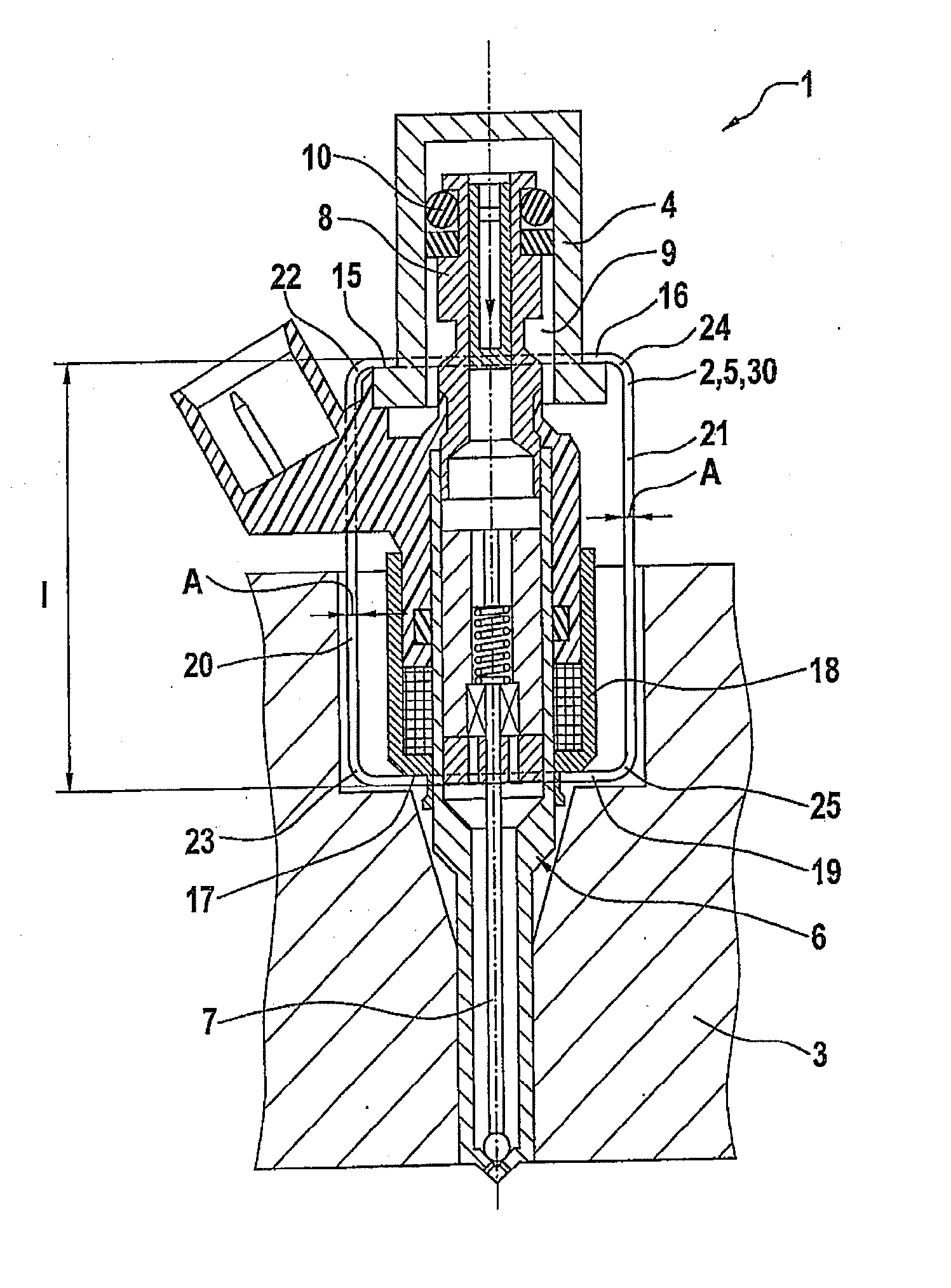
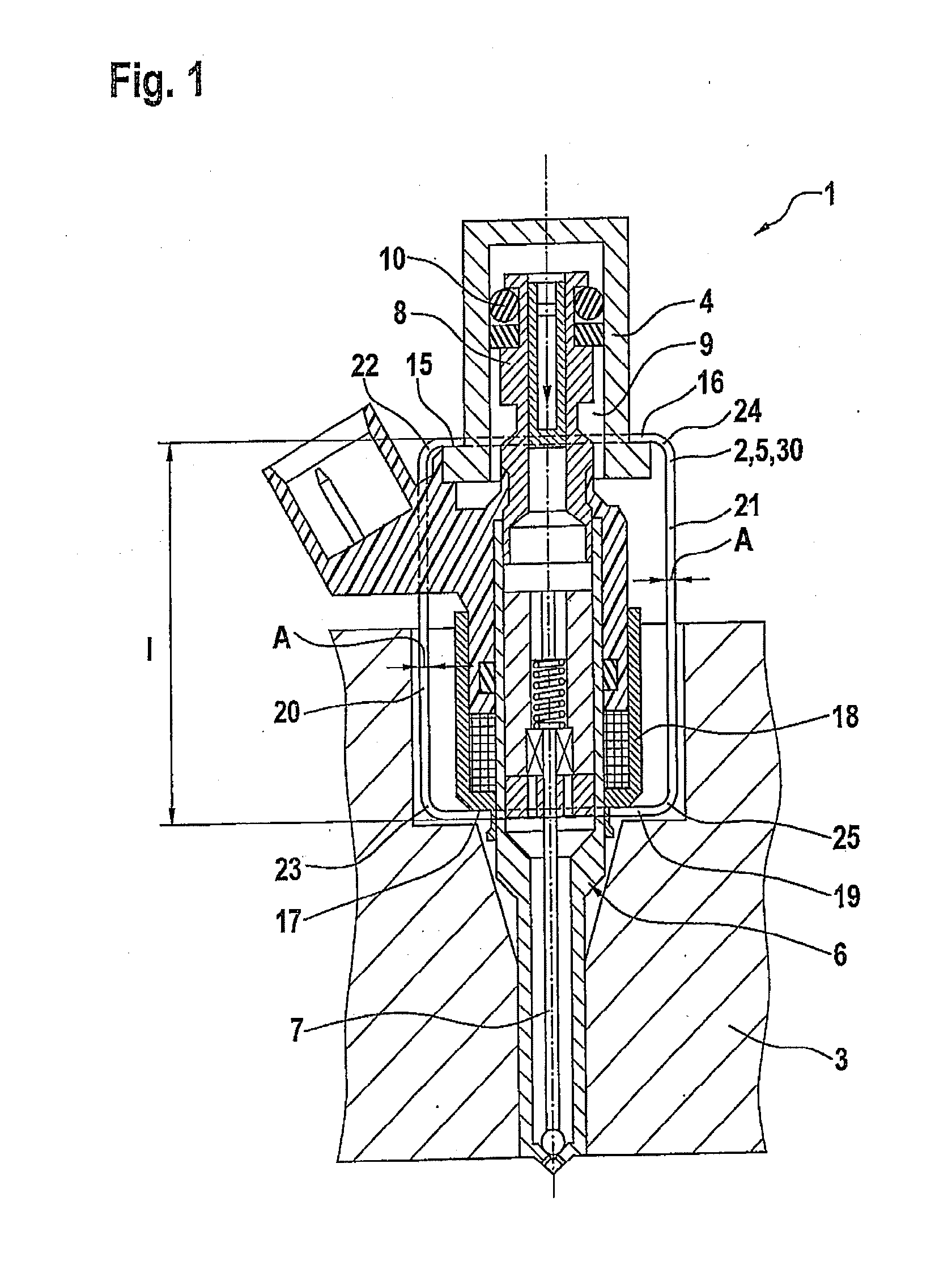
[0018]FIG. 1 shows a fuel injection system 1 having a connecting device 2 corresponding to a first exemplary embodiment and an internal combustion engine 3 in an excerpted, schematic sectional representation. Fuel injection system 1 may be particularly used for high-pressure injection in internal combustion engines 3. In particular, fuel injection system 1 may be used in mixture compressing internal combustion engines 3 having externally supplied ignition. Connecting device 2 is particularly suitable for such a fuel injection system 1.

[0019]Fuel injection system 1 has a fuel-carrying component 4. In this case, in FIG. 1, a cup 4 of fuel-carrying component 4 is shown which, for example, is a component of a fuel manifold.

[0020]Connecting device 2 has a wire-shaped connecting element 5, which is embodied to be closed in an annular fashion. In this instance, connecting device 2 has a still further connecting element, for example, which is embodied corresponding to connecting element 5. ...


PUM


Abstract

A connecting device for fuel injection systems is used for connecting a fuel injection valve to a fuel-carrying component. A wire-shaped connecting element is provided in this context, which is fastened, on the one hand, to the fuel-carrying component and, on the other hand, to the fuel injection valve. The wire-shaped connecting element is embodied closed in an annular manner, and, on the one hand, is guided about a shoulder of the fuel-carrying component and, on the other hand, about a shoulder of the fuel injection valve. A fuel injection system having such a connecting device is also provided.

Description

FIELD OF THE INVENTION[0001]The present invention relates to a connecting device for fuel injection systems for the connection of a fuel injector to a fuel-carrying component and a fuel injection system having such a connecting device. The present invention particularly relates to the field of fuel injection systems for mixture-compressing internal combustion engines having externally supplied ignition.[0002]BACKGROUND INFORMATION[0003]A fuel injection system is known, from German Published Patent Appln. No. 29 08 095, for internal combustion engines having a plurality of fuel injectors, of which each, at its one end, is connected via a connection piece in a sealing manner to a barb nipple of an in-common, dimensionally stable, fuel distributor line, and has an orifice at another end. In this instance, each fuel injector is connected to the fuel distributor line by respectively one flexible, appropriately formed retaining clip which encompasses the fuel distributor and the fuel dist...

Claims


Application Information

Patent Timeline
IPC IPC(8): F02M61/14
CPCF02M61/14F02M51/0671F02M55/004F02M55/005F02M2200/09F02M2200/853F02M2200/856
Inventor FISCHER, MICHAELKNORPP, MICHAELRIEMER, MARTINHORST, HANS-GEORGGLASER, ANDREASROGLER, PHILIPPHERRMANN, JANREHWALD, ANDREASMAYER, MICHAELSCHEEF, VOLKERREINHARDT, WILHELM
Owner ROBERT BOSCH GMBH
Why Eureka
Try Eureka