Worm speed reducer and electric power steering device
- Summary
- Abstract
- Description
- Claims
- Application Information
AI Technical Summary
Benefits of technology
Problems solved by technology
Method used
Image
Examples
example 1
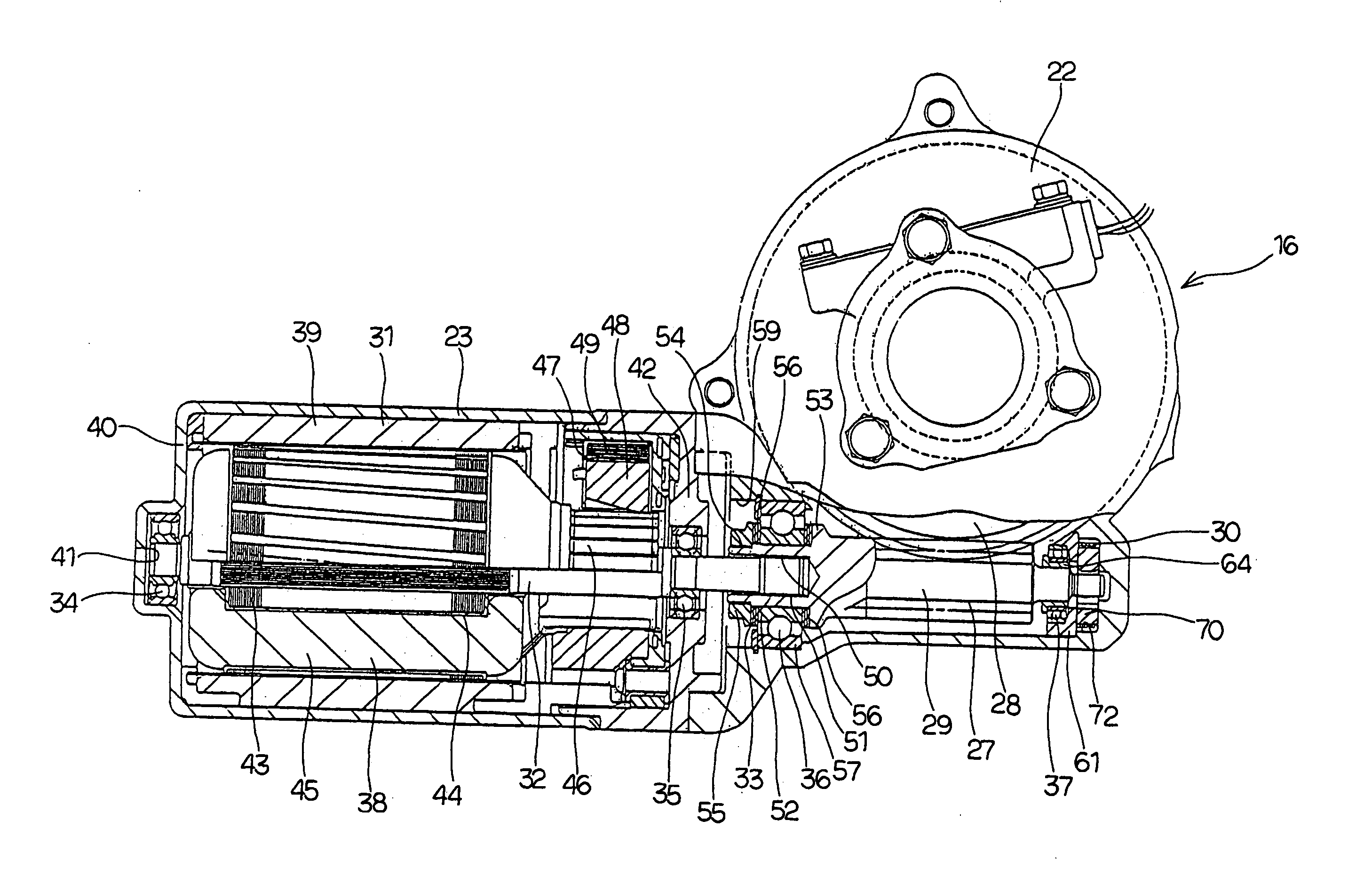
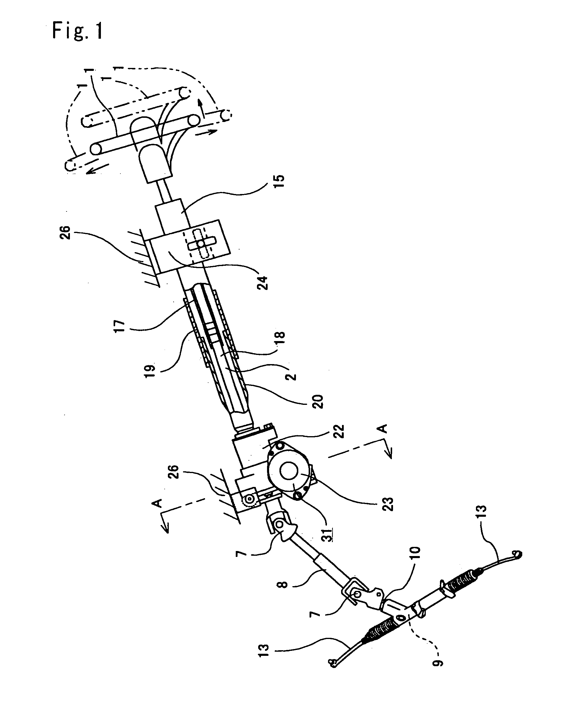
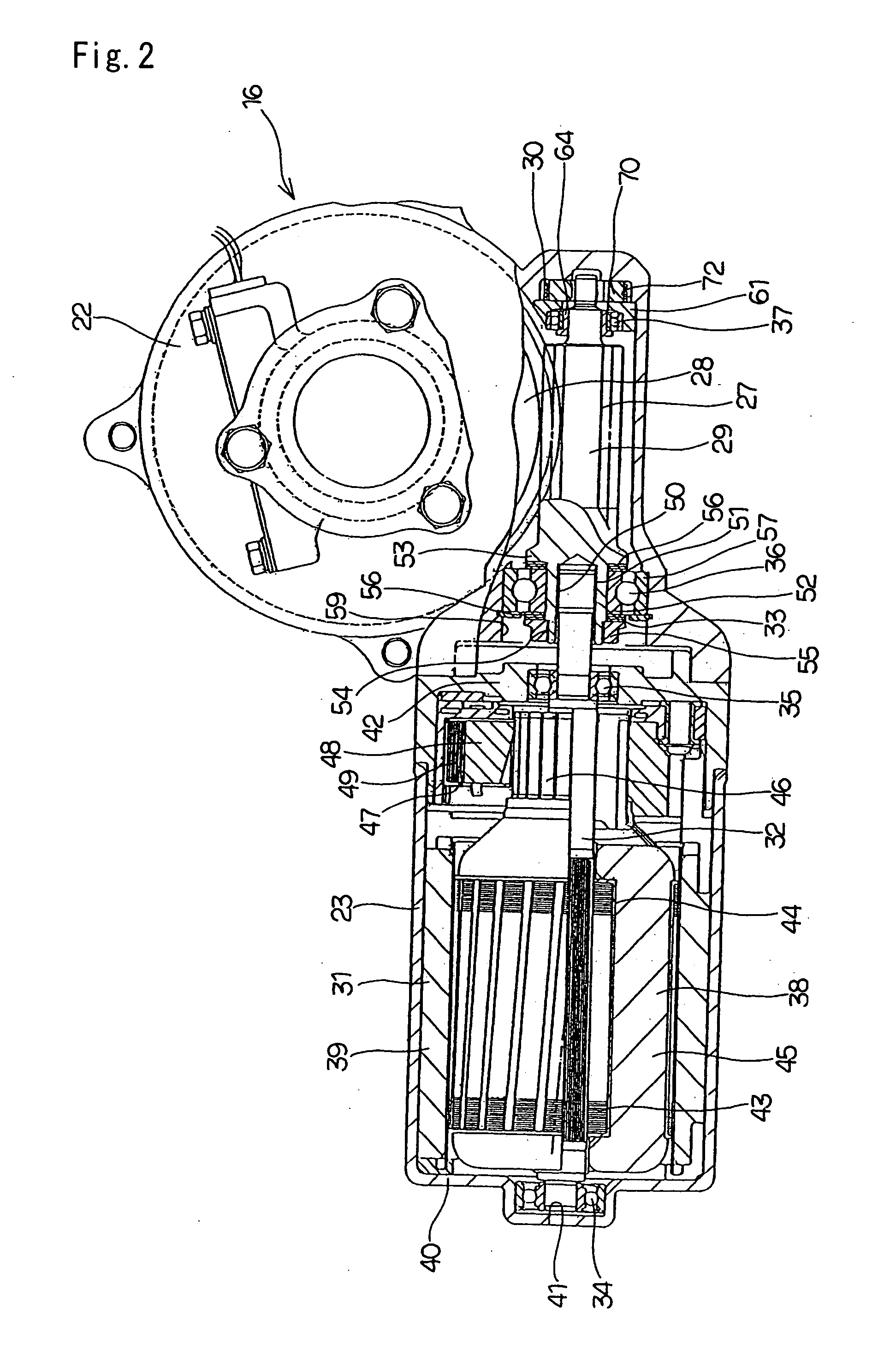
[0150] FIGS. 1 to 9 show a first example of the present invention. The electric power steering apparatus of this example comprises: a steering shaft 2 being an assist shaft which is secured at a rear end portion to a steering wheel 1; a steering column 15 through which the steering shaft 2 passes freely; a worm reduction gear 16 for applying a supplementary torque to the steering shaft 2; a pinion 11 (refer to FIG. 46) provided on the front end of the steering shaft 2; a rack 12 (refer to FIG. 46) which is meshed with the pinion 11 or with a member supported on the pinion 11; a torque sensor 3 (refer to FIG. 46); an electric motor 31; and a controller 6 (refer to FIG. 46).
[0151] The steering shaft 2 is made by assembling an outer shaft 17 and an inner shaft 18 by a spline engaging section so as to freely transmit a rotation force and enable axial movement. Moreover, in the case of this example, the front end portion of the outer shaft 17 and the rear end portion of the inner shaft ...
example 2
[0174] Next, FIG. 10 shows a second example of the present invention. In the case of this example, the position of contact portions 94a between an inner peripheral face of a through hole 71a provided in a pre-load pad 70, and an outer peripheral face of a small diameter portion 68 provided on the tip end portion of a worm shaft 29 is different to the case of the aforementioned first example. That is to say, in the case of this example, the contact portions 94a between the worm shaft 29 and the pre-load pad 70 are provided at three locations evenly spaced around the circumferential direction, being symmetric in relation to the direction of arrow (a) in FIG. 10 being the direction of action of the reaction force in a direction perpendicular to the central axis of the worm shaft 29, for a predetermined rotation direction of the worm wheel 28 where the reaction force applied from the worm wheel 28 (refer to FIGS. 4 and 5) to the worm shaft 29 tends to be large.
[0175] In the case of thi...
example 3
[0176] Next, FIGS. 11 and 12 show a third example of the present invention. In the case of this example, a pre-load pad 70a is constructed by assembling together two different elements 110a and 100b. These two elements 110a and 110b have the discontinuous portion 90 of the pre-load pad 70 which constitutes the construction of the first example shown in FIGS. 1 to 9, provided centrally in the widthwise direction, and have a shape obtained by cutting the pre-load pad 70 at a position on the opposite side to the discontinuous portion 90 in relation to the central axis of the through hole 71 (refer to FIG. 7). That is to say, each of the elements 110a and 110b are respectively provided with concave portions 111 of an approximately half cylindrical shape in an intermediate portion in the length direction (the up and down direction in FIGS. 11 and 12) of one side face facing each other, and planar portions 112a and 112b on portions at both ends in the length direction. Furthermore, on the...
PUM
 Abstract
Description
Claims
Application Information
 - R&D
- Intellectual Property
- Life Sciences
- Materials
- Tech Scout
- Unparalleled Data Quality
- Higher Quality Content
- 60% Fewer Hallucinations
Browse by: Latest US Patents, China's latest patents, Technical Efficacy Thesaurus, Application Domain, Technology Topic, Popular Technical Reports.
© 2025 PatSnap. All rights reserved.Legal|Privacy policy|Modern Slavery Act Transparency Statement|Sitemap|About US| Contact US: help@patsnap.com


