
Hinge mechanism for a foldable electronic device

a technology of electronic devices and hinges, applied in the direction of wing openers, multi-purpose tools, constructions, etc., to achieve the effect of reducing or eliminating friction and saving energy

Inactive Publication Date: 2006-06-08
SHENZHEN FUTAIHONG PRECISION IND CO LTD +1
View PDF8 Cites 14 Cited by
  • Summary
  • Abstract
  • Description
  • Claims
  • Application Information

AI Technical Summary

Benefits of technology

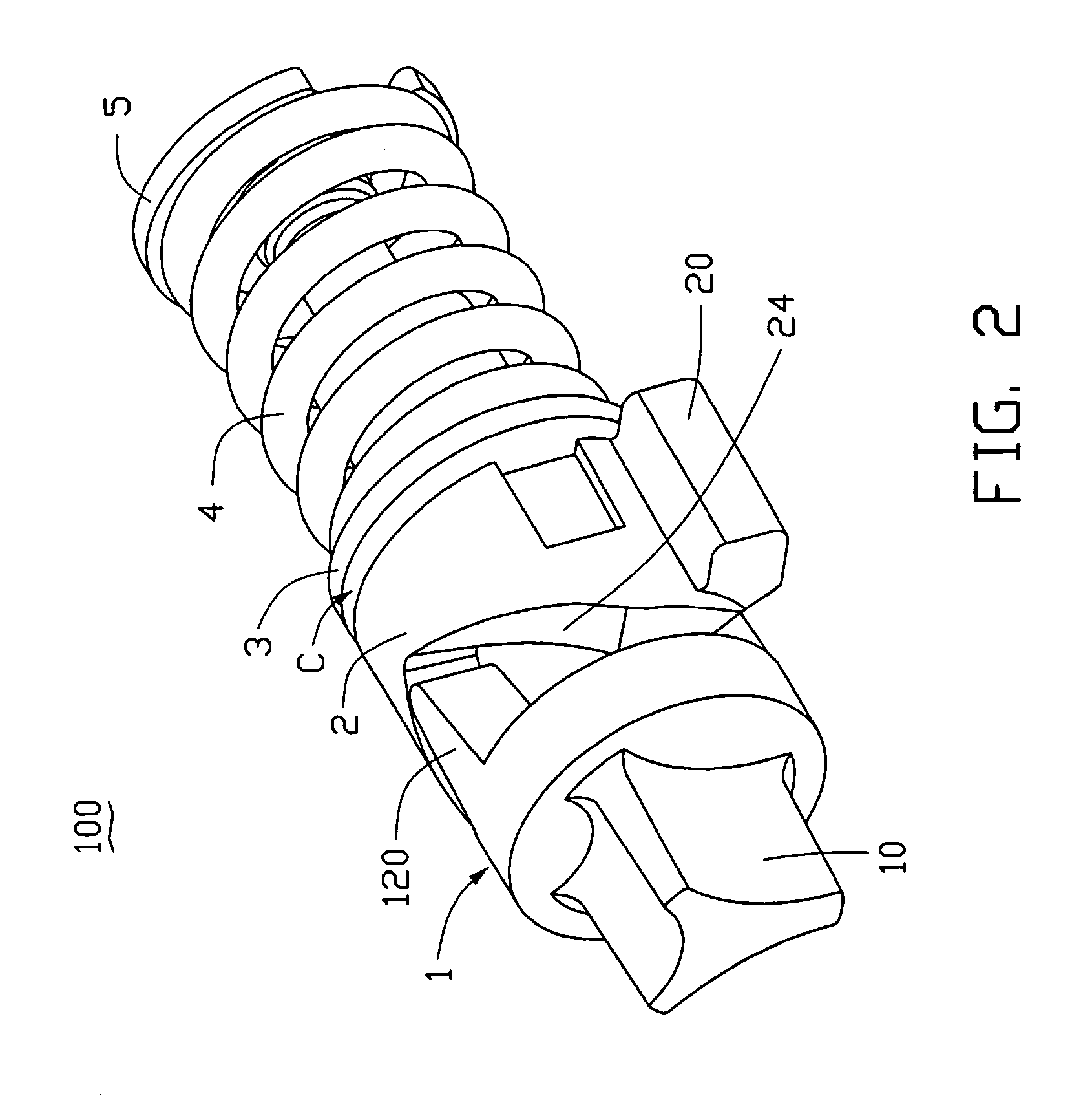
[0010] When opening the cover, the cam rotates relative to the washer. There is a space or clearance that exists between the cam and the washer due to the repulsive nature of having the same polarity face-to-face. Therefore, the matched polarity faces will reduce or eliminate friction and save energy. Thus, the hinge mechanism should serve longer and run more stably over that time span.

Problems solved by technology

There is a space or clearance that exists between the cam and the washer due to the repulsive nature of having the same polarity face-to-face.

Method used


Image

  • Hinge mechanism for a foldable electronic device
  • Hinge mechanism for a foldable electronic device
  • Hinge mechanism for a foldable electronic device

Examples


Embodiment Construction

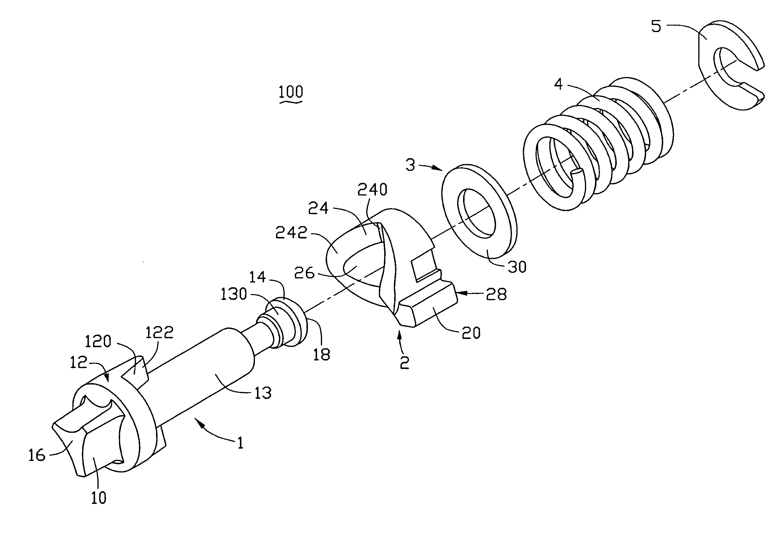
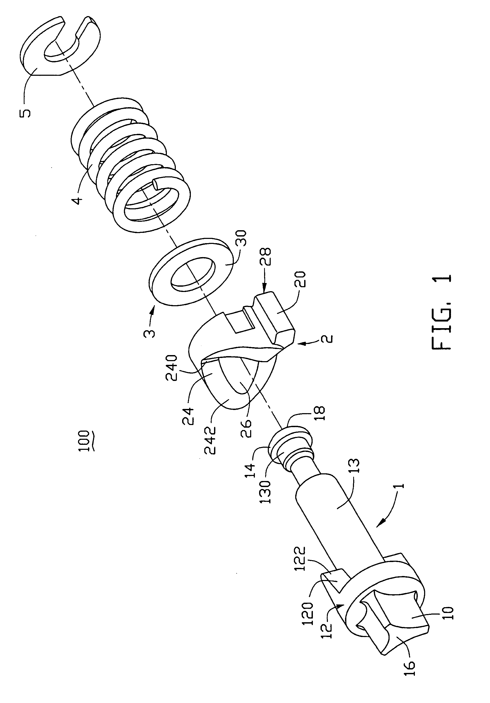
[0017] Referring to FIG. 1, a hinge mechanism 100 includes a shaft 1, a cam 2, a washer 3, a spring 4 and a ring 5.

[0018] The shaft 1 includes a stop portion 10, a rotating portion 12 (i.e., cam follower), a shaft portion 13 and a flange 14, arranged in turn. The shaft 1 has a first shaft end 16 and an opposite second shaft end 18. The stop portion 10 is formed at the first shaft end 16, and the flange 14 is formed at the second shaft end 18. Two projections or extensions 120, each with a tip 122 on the top (i.e., distal portion) thereof, extend axially and symmetrically from the rotating portion 12. A small shaft 130 is disposed adjacent to the flange 14. A diameter of the small shaft 130 is smaller than that of the shaft portion 13 and the flange 14.

[0019] The cam 2 is column-shaped with a through hole 26 running though and along a center axis thereof. A rib 20 is formed on the outside wall of the cam 2. A cam surface 24 is formed on one end of the cam 2. The cam surface 24 incl...


PUM


Abstract

A hinge mechanism includes a shaft (1), at least one cam follower (12), a cam (2), a washer (3) and an elastic member (4). Each cam follower has a projection (120) connected to the shaft. The cam has a cam surface (24) defined thereon. The shaft runs through the cam, the washer and the elastic member, in turn. The cam surface of the cam faces the projection of each cam follower, and the cam abuts the cam follower, due to the spring force generated by the elastic member. The washer and the cam are magnetic, the facing portions thereof having the same polarity. As a result of the repulsive magnetic force between the cam and washer, the hinge mechanism generates a smaller friction therebetween, so the waste of energy is very small. The present hinge mechanism can be used in foldable electronic devices.

Description

BACKGROUND OF THE INVENTION [0001] 1. Field of the Invention [0002] The present invention generally relates to hinge mechanisms and, more particularly, to a hinge mechanism for hinging together housings of a foldable, portable electronic device such as a mobile phone or a PDA (Personal Digital Assistant). [0003] 2. Discussion of the Related Art [0004] Portable mobile phones generally have two housings rotatably joined by a type of hinge that allows the housings to fold upon one another. Many such foldable mobile phones have most of the electronics in one housing, called the main housing, and fewer electronics in the other housing, called the cover. Other such foldable mobile phones have all the electronics in the main housing, with the cover serving only to cover a keypad and a display of the main housing. The main housing and the cover are connected together by a hinge mechanism. Generally, the opening or closing of most covers is achieved by means of a cam mechanism and a spring o...

Claims


Application Information

Patent Timeline
Patent Type & Authority Applications(United States)
IPC IPC(8): E05F1/08
CPCE05F1/1016Y10T16/5387E05Y2900/606E05F1/1223E05Y2999/00
Inventor TU, YING-LIANGDUAN, CHAOJIANG, MAO-FAOU-YANG, QINWEN, ZHENG-FANGCHEN, CHIA-HUA
Owner SHENZHEN FUTAIHONG PRECISION IND CO LTD
Learn More