
In-band control of indicators to identify devices distributed on the same domain

a technology of in-band control and indicators, applied in the direction of time-division multiplex, electrical apparatus, error identification, etc., can solve the problems of increasing complexity and inability to determine which enclosure houses the failed components

Inactive Publication Date: 2006-06-01
IBM CORP
View PDF5 Cites 176 Cited by
  • Summary
  • Abstract
  • Description
  • Claims
  • Application Information

AI Technical Summary

Benefits of technology

[0005] The present invention provides systems, methods and a computer program product to permit the identification of all of the devices of a specified domain in a multi-domain environment. Moreover, all communication among the domain devices is in-band having the advantage that no additional cabling is required.
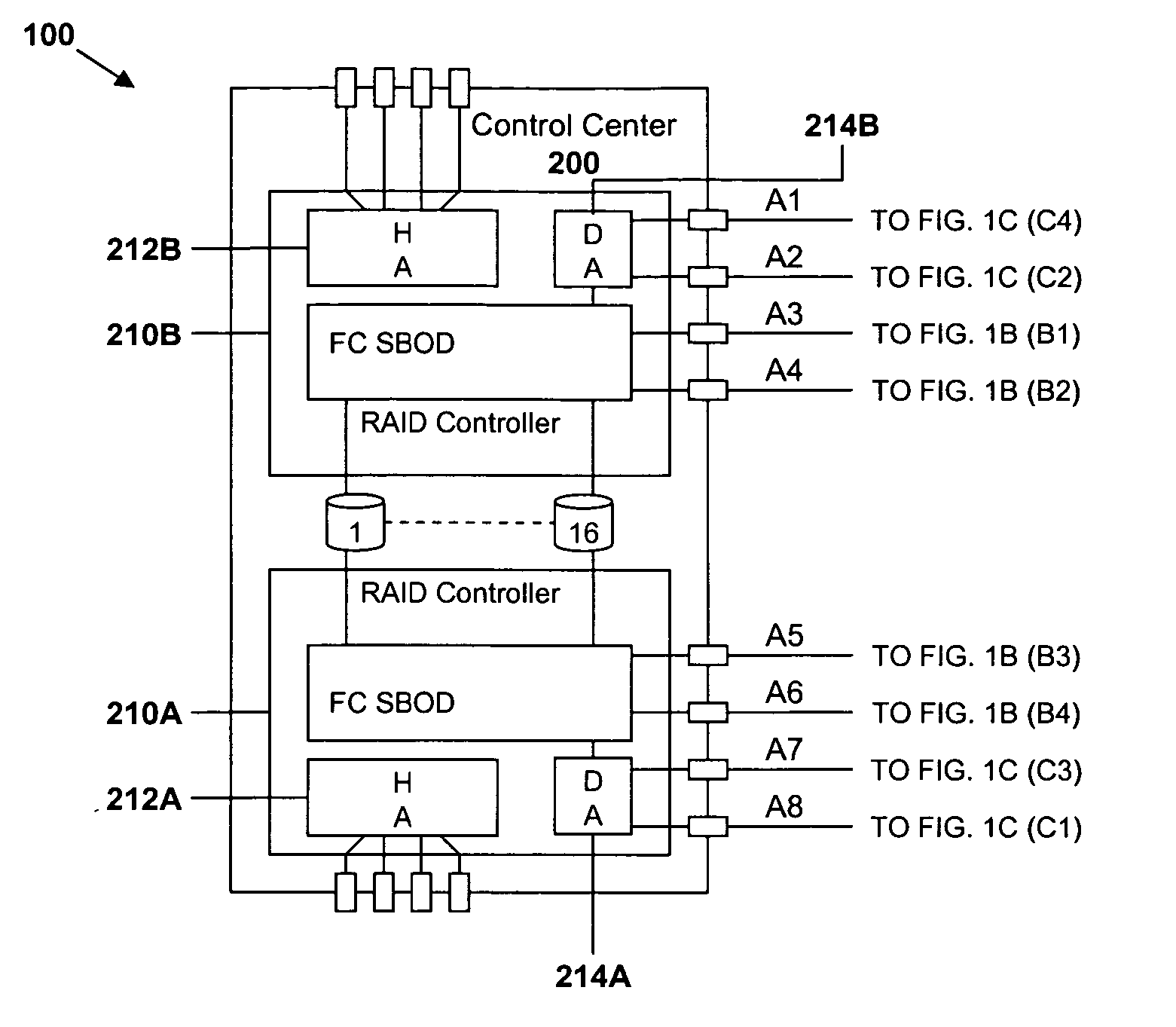
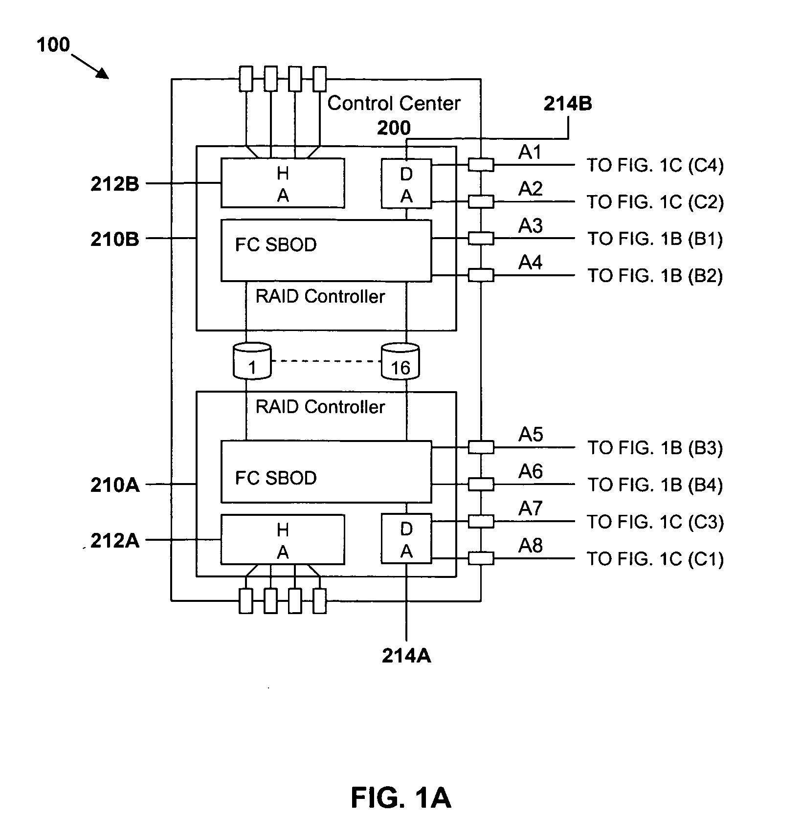
[0006] The present invention may be incorporated into the control center through which host / domain communications are routed or may be incorporated into any other dedicated or multi-purpose unit or units to which the domains are attached. In operation, the control center receives an in-band command from an initiating device in a specified domain, the command being transmitted in response to the activation of a triggering device on the initiating device. Upon receipt of the command, the control center broadcasts an in-band command to each of the other devices in the domain directing the other devices to activate an indicator on each of the other devices. With the indicators on the devices in the specified domain activated, the administrator is able to identify those devices and thus focus his search for the faulty device only on those devices within the domain.

Problems solved by technology

The flexibility of a user-configured, rack mounted facility can eventually result in increasing complexity.
When a disk drive or other component fails, the facility administrator may be able to identify the domain in which the failed component exists but may not be able to determine which enclosure houses the failed component.

Method used


Image

  • In-band control of indicators to identify devices distributed on the same domain
  • In-band control of indicators to identify devices distributed on the same domain
  • In-band control of indicators to identify devices distributed on the same domain

Examples


Embodiment Construction

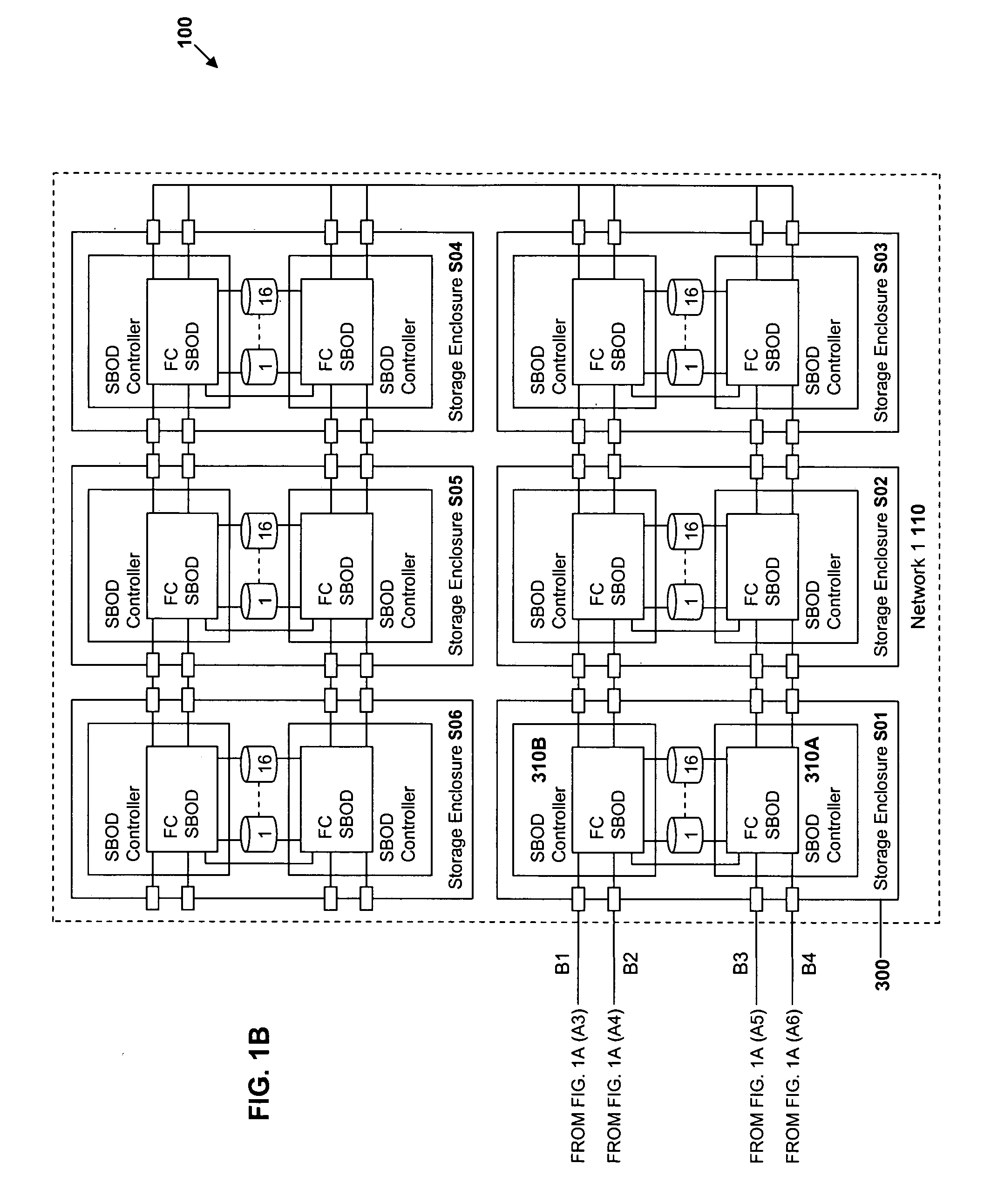
[0014]FIG. 1 is a block diagram of an exemplary two-network domain 100 in which the present invention may be implemented. The domain 100 in the FIG. includes a control center 200 and two exemplary networks 110 and 120. Each network includes a plurality of storage enclosures, such as enclosure S01300 in the first network 110. In FIG. 1, the control center 200 and storage enclosures 300 (also referred to herein as “devices”) each comprise two clusters in a known configuration. A first cluster 210A in the control center 200 is interconnected with a first cluster in each of the storage enclosures in both networks 110 and 120, such as a first cluster 310A of enclosure S01 of the first network 110, and a second cluster 210B in the control center is interconnected with a second cluster in each of the storage enclosures in both networks 110 and 120, such as a second cluster 310B of enclosure S01 of the first network 110. The storage enclosures in the first network 110 may be daisy chained u...


PUM


Abstract

Systems, methods and a computer program product are provided to permit the identification of all of the devices of a specified domain in a multi-domain environment. All communication among the domain devices is in-band having the advantage that no additional cabling is required. A control center between host devices and the domains receives an in-band command from an initiating device in a specified domain, the command being transmitted in response to the activation of a triggering device on the initiating device. Upon receipt of the command, the control center broadcasts an in-band command to each of the other devices in the domain directing the other devices to activate an indicator on each of the other devices. With the indicators on the devices in the specified domain activated, an administrator is able to identify those devices and thus focus his search for the faulty device only on those devices within the domain.

Description

TECHNICAL FIELD [0001] The present invention relates generally to networks of devices distributed across multiple domains and, in particular, to identifying which devices in a multi-domain environment are attached to a particular domain. BACKGROUND ART [0002] Large, enterprise-scale computing facilities include one or more host devices to which are attached several (or many) data storage devices. The IBM® TotalStorage® DS6000 storage server is an example of one such device. The DS6000 provides modular storage with distributed enclosure racks which may be easily installed and subsequently relocated by a customer. Enclosures are mounted in the racks to provide an efficient and standardized method of physically organizing the various components. Additionally, the use of rack mounted enclosures allows the customer to place the components in the racks and arrange them in the computing facility in a flexible manner. Each server enclosure may be configured into two (or more) clusters shari...

Claims


Application Information

Patent Timeline
IPC IPC(8): H04J3/22
CPCG06F11/006
Inventor LUCAS, GREGG S.KUBO, ROBERT A.CURNALIA, MICHAEL A.COX, AARON R.BOMHOFF, MATTHEW D.
Owner IBM CORP
Learn More