
Fault-tolerant electromechanical actuator having a torque sensing control system

a torque sensing control system and electromechanical actuator technology, applied in the direction of gearing, device details, piezoelectric/electrostrictive device details, etc., can solve the problems of increasing design complexity, adding weight, and the required plumbing to distribute and control the pressurized working fluid, so as to achieve effective prevention of actuator failure and low cost

Active Publication Date: 2006-06-01
THE BOEING CO
View PDF18 Cites 107 Cited by
  • Summary
  • Abstract
  • Description
  • Claims
  • Application Information

AI Technical Summary

Benefits of technology

[0010] The EMA provides a fault tolerant actuator having low cost, accurate torque sensing system to detect friction within a motor module of the EMA to provide reliable redundancy within the EMA to effectively prevent failure of the actuator and potentially hazardous conditions that could result from such a failure.

Problems solved by technology

A drawback with hydraulic actuators is the plumbing required to distribute and control the pressurized working fluid.
For example, in an aircraft, a pump that generates high-pressure working fluid and the plumbing required to route the working fluid add weight and increase design complexity because the hydraulic lines must be carefully routed.
Electric actuators, which are powered and controlled by electric energy, require only wires to operate and control but a drawback with prior art electrical actuators can be their reliability.
Windings of electrical motors are susceptible to damage from heat and water.
Bearings on motor shafts wear out.
The transmission between the motor and the load, and which is inherently more complex than the piston and cylinder used in a hydraulic actuator, is also susceptible to wear and tear, and eventually to failure.

Method used


Image

  • Fault-tolerant electromechanical actuator having a torque sensing control system
  • Fault-tolerant electromechanical actuator having a torque sensing control system
  • Fault-tolerant electromechanical actuator having a torque sensing control system

Examples


Embodiment Construction

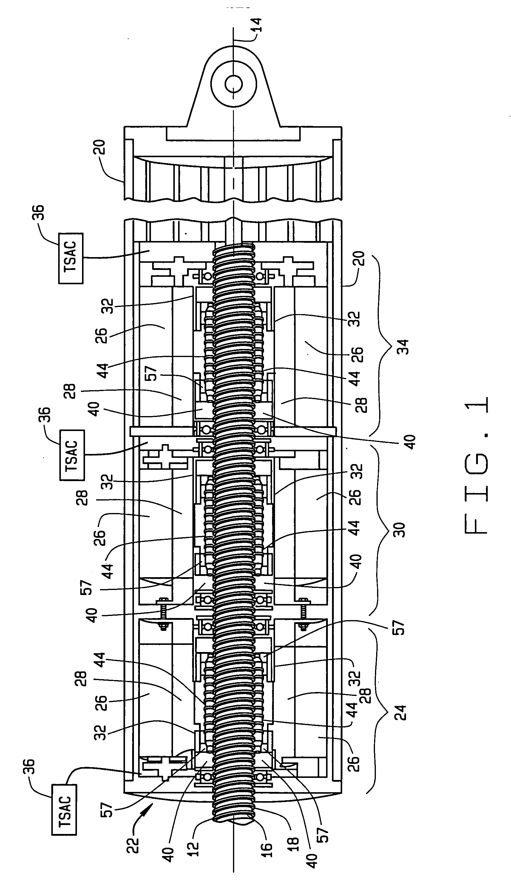
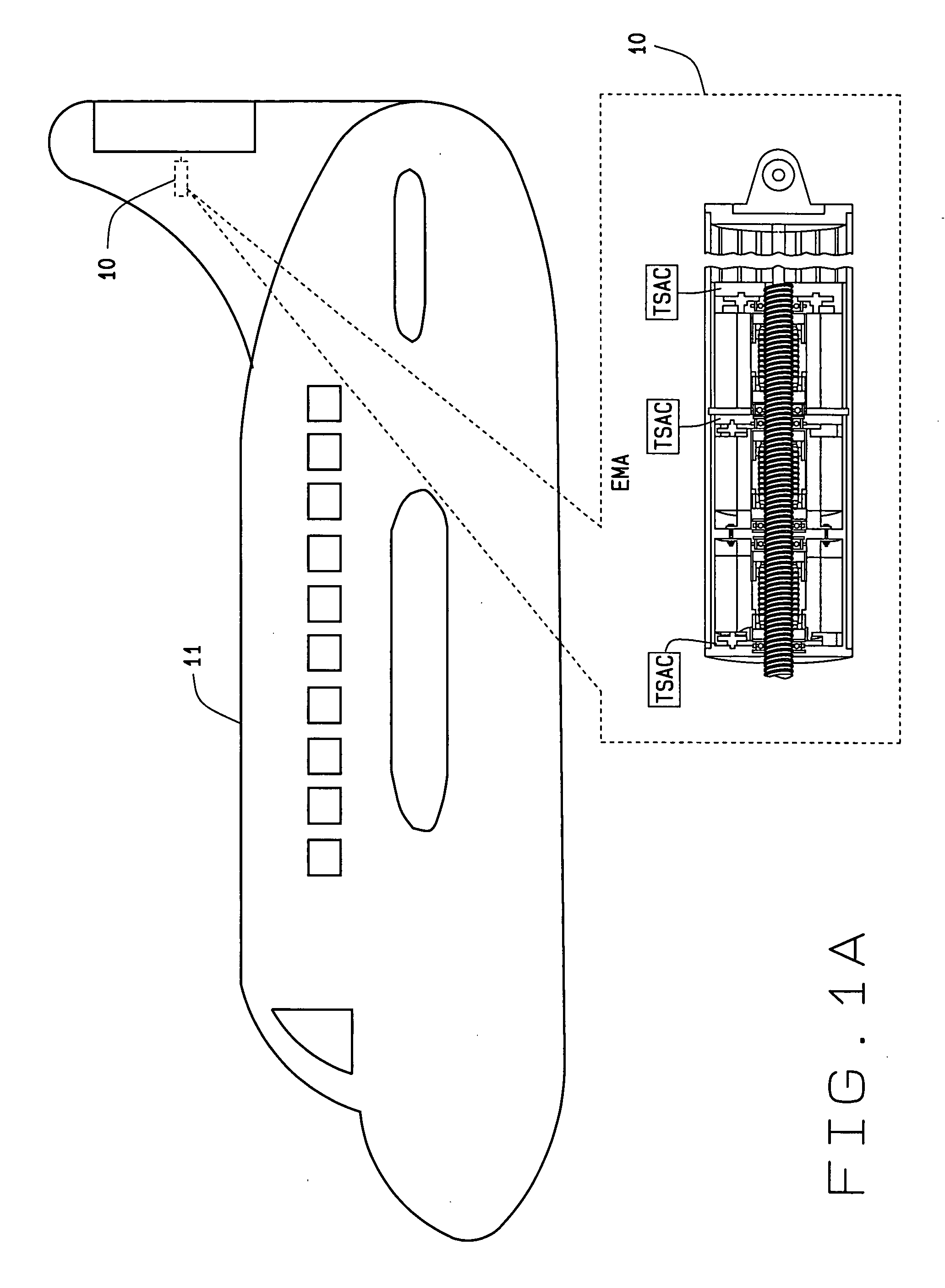
[0041]FIG. 1 is a cross-sectional view of an electrically powered and fault tolerant electrical actuator 10, in accordance with various embodiments. The fault tolerant electrical actuator 10 can be utilized in various applications to control the movement of one or more mechanical components, devices or machines. For example, the fault tolerant electrical actuator 10 can be implemented in a mobile platform 11, exemplarily shown as an aircraft, to control the movement of mobile platform control mechanisms or surfaces. For example, the mobile platform 11 can be an aircraft that utilizes the fault tolerant electrical actuator 10 to control the movement of flaps, spoilers and ailerons in each wing during operation of the aircraft. Although mobile platform 11 is illustratively shown as an aircraft, the mobile platform 11 can be any mobile platform inclusive of, but not limited to, an aircraft, a bus, a train or a ship.

[0042] Generally, the actuator 10 is comprises a cylindrically-shaped ...


PUM


Abstract

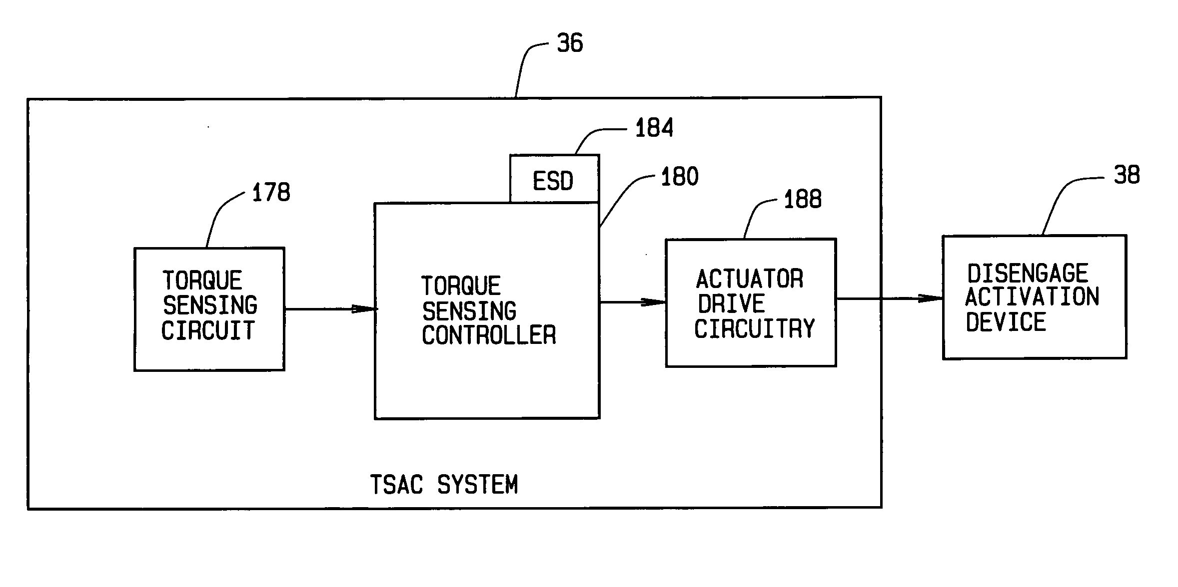
An electromechanical actuator (EMA) is provided. The EMA includes a threaded output ram connectable to a mechanical component and at least one motor module engageable with the output ram for controllably translating the output ram along a linear axis of the output ram. The actuator further includes a torque sensing adaptive control (TSAC) system for monitoring torque within the motor module. The TSAC generates a disengagement command signal when the TSAC system determines torque within the motor module is outside an allowable motor module torque range. The disengagement command signal initiates disengagement of the motor module from the output ram.

Description

CROSS REFERENCE TO RELATED APPLICATIONS [0001] This application is a continuation / continuation-in-part of U.S. patent application Ser. No. 10 / 860,931 filed on Jun. 4, 2004. The disclosure of the above application is incorporated herein by reference.FIELD OF INVENTION [0002] The invention relates generally to electromechanical actuators for controlling movement of mechanical components, devices or machines. BACKGROUND OF THE INVENTION [0003] This invention relates to actuators. An “actuator” is defined in the Merriam-Webster's Collegiate Dictionary, Tenth Edition as a mechanical device for moving or controlling something. Actuators perform a myriad of functions and enable many modern conveniences. [0004] Various mobile platforms, e.g. aircraft, buses, trains, ships and various other vehicles, use actuators to perform many functions during operation of the mobile platform. For example, aircraft utilize actuators to control the movement of flaps, spoilers and ailerons in each wing duri...

Claims


Application Information

Patent Timeline
IPC IPC(8): H02P7/00H02K7/06H01L41/04H02K7/10B64C13/00B64C13/24F16H25/20F16H27/02H02K16/00H02K19/38H02K41/00
CPCB64C13/00Y10T74/186F16H25/2015F16H25/2025F16H25/2252F16H2025/2071F16H2025/2078H02K7/06H02K7/108H02K7/116H02K11/0042H02K11/0057H02K16/00Y02T50/44B64C13/24H02K11/24H02K11/27Y02T50/40
Inventor BLANDING, DAVID E.PECK, JAMES LEO
Owner THE BOEING CO
Learn More