
Articulated crawler tractor

a crawler and trawler technology, applied in the field of crawler dozers, can solve the problems of poor visibility of the conventional dozer blade, risk of vehicle tilting, difficulty in side-sloping dozing, etc., and achieve the effect of increasing the number of track units, improving traction, and increasing the effective traction

Inactive Publication Date: 2006-06-01
DEERE & CO
View PDF5 Cites 43 Cited by
  • Summary
  • Abstract
  • Description
  • Claims
  • Application Information

AI Technical Summary

Benefits of technology

[0003] The track / steering system has been demonstrated to be the best method of transferring high tractive efforts to the ground while minimizing power losses due to steering. This has been demonstrated during scraper tractor comparisons which have included both 2 track systems (Cat Challenger, Deere 9000T) as well as 4 track articulated machines (Case IH Quad Track).
[0005] Improvement in traction is achieved by a decrease in the length of each independently suspended track unit contacting the ground coupled with an increase in the number of track units as compared to the 2-track crawler. Having four separate, smaller track units results in an increase in the effective traction because more track is actually contacting soil than with a conventional crawler, especially on uneven soil surfaces. Such a configuration allows the machine weight and cost to be reduced for equivalent machine performance and improves the ride of the vehicle.
[0006] A crawler dozer frequently operates on sloped surfaces. To maximize the ability to safely operate on side slopes, a unique configuration is utilized. The front suspension system is designed to eliminate roll at the front axle. The rear axle provides the necessary axle oscillation required to maintain ground contact on uneven surfaces. Further, as mentioned above, the center of gravity for the machine is very low.
[0007] Thus, the vehicle described and claimed herein is, in comparison to more conventional machines, narrower, more stable (even on slopes), lighter, a better ride, and has greater amount of ground contact. Additional, blade visibility is improved over conventional two track crawlers.

Problems solved by technology

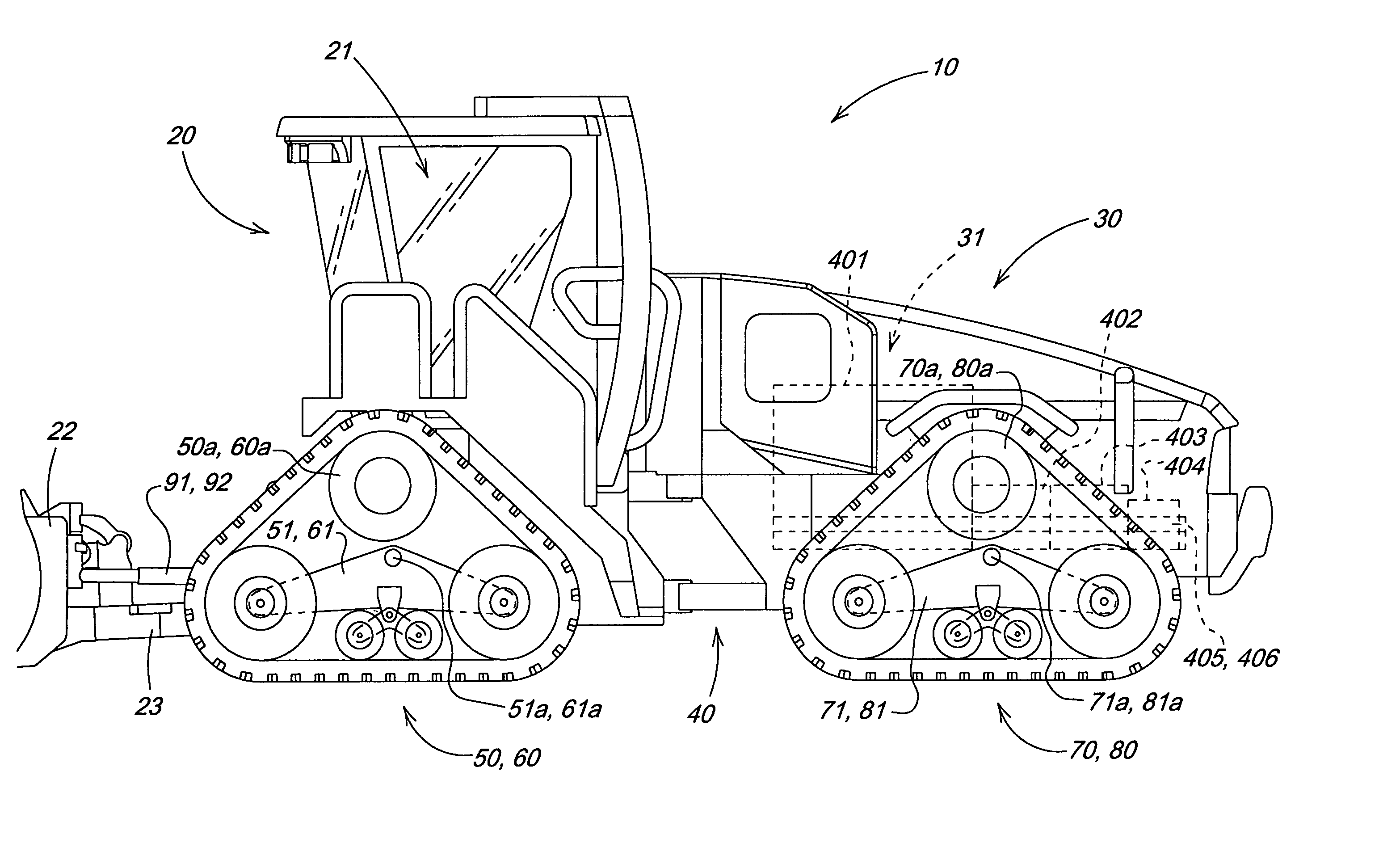
Conventional dozers have poor visibility with respect to the dozer blades; traditionally, only the ends of the blade are visible from the cab of a dozer as the view is obstructed by the front (i.e., the hood, etc.) of the vehicle.
Moreover, conventional dozers have a high center of gravity as the center of gravity for the engine and pumps tend to be high, making it difficult to doze sideways on a slope due to an increased risk of vehicle tilting.

Method used


Image

  • Articulated crawler tractor
  • Articulated crawler tractor
  • Articulated crawler tractor

Examples


Embodiment Construction

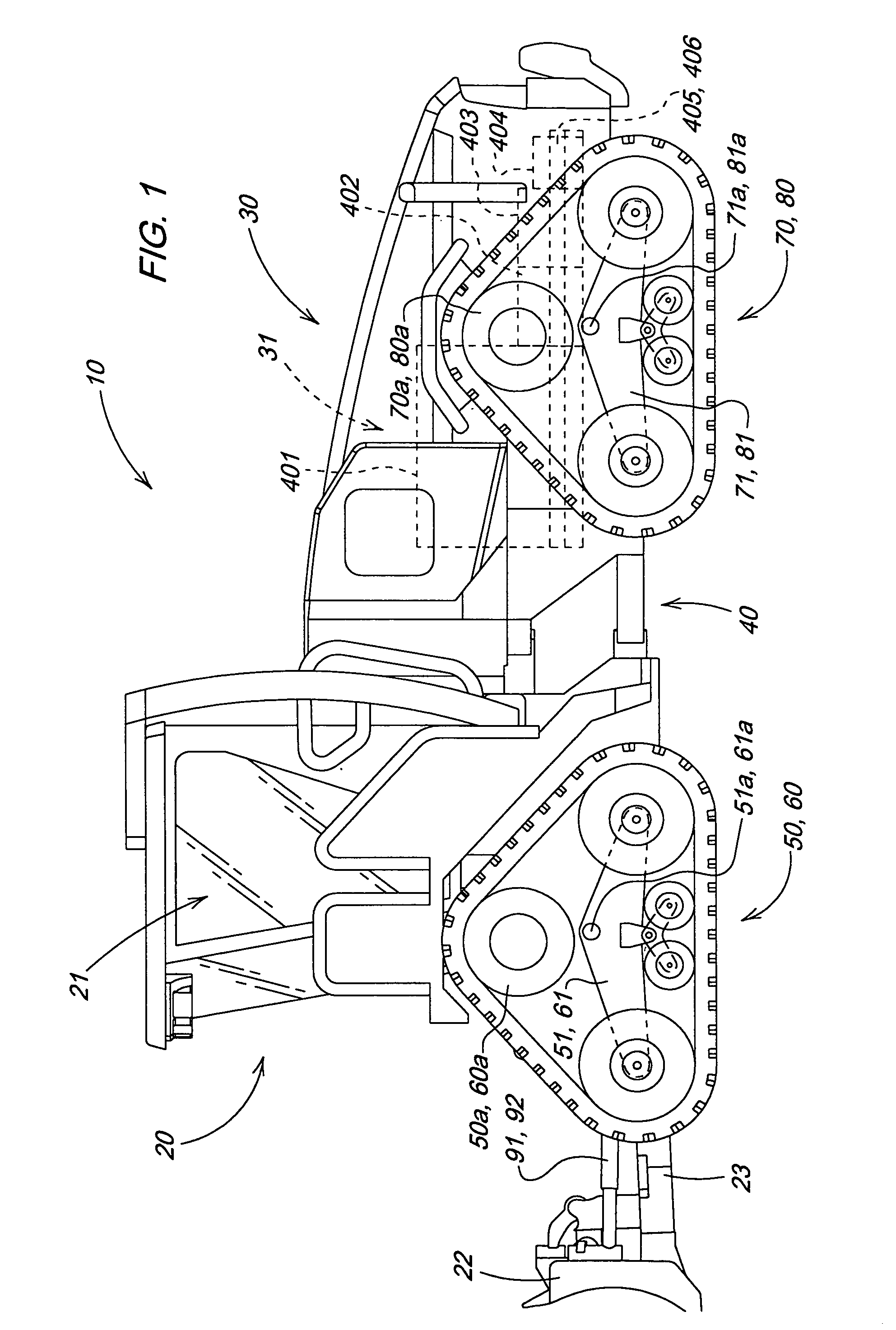
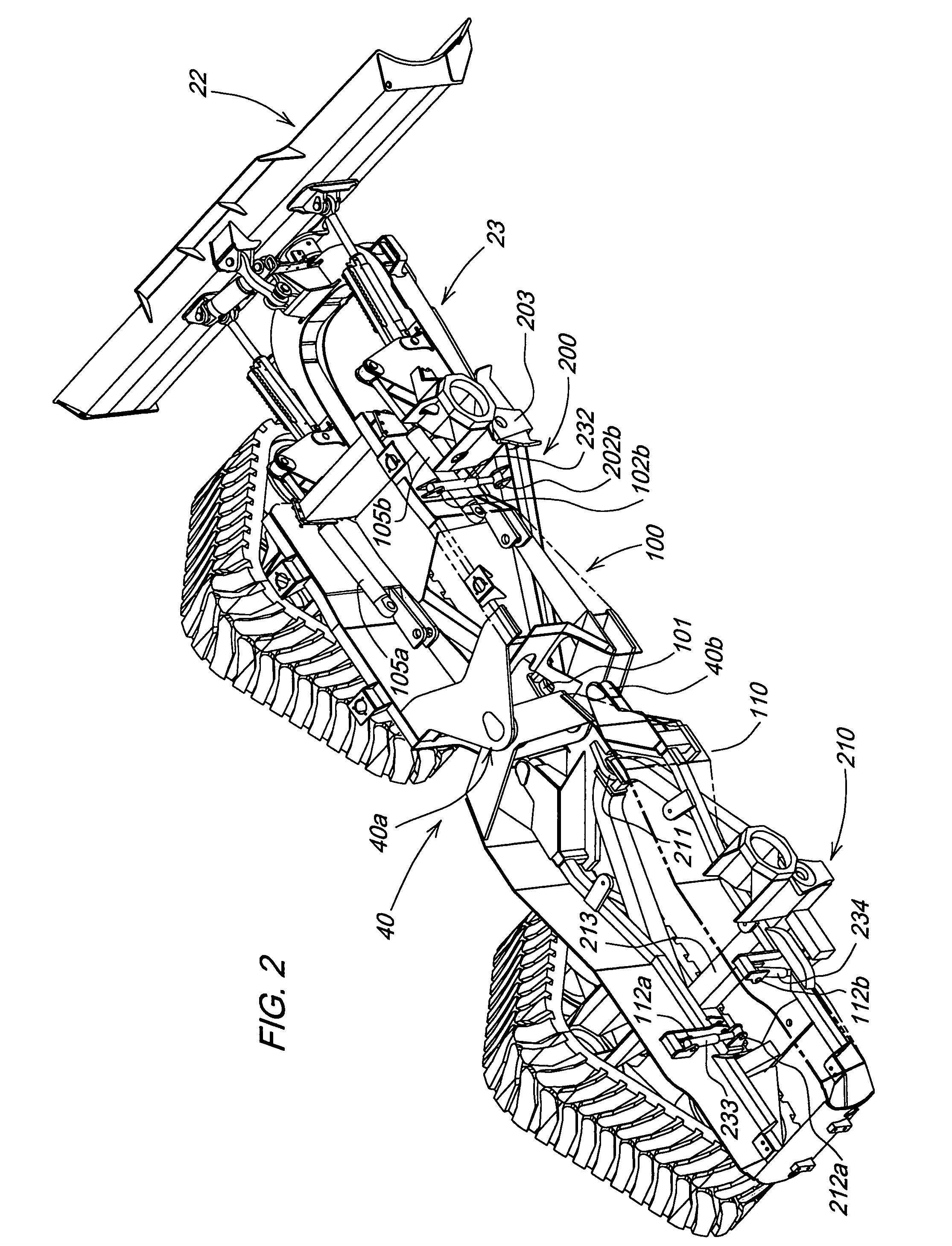
[0018]FIGS. 1 and 9 illustrate an exemplary embodiment of the invention. The particular vehicle illustrated in FIGS. 1 and 1 is a four track articulated dozer 10 having a front portion 20 a rear portion 30; a conventional articulation mechanism 40 between the front portion 20 and the rear portion 30; first and second track systems 50, 60; and third and fourth track systems 70, 80. The front portion 20 includes a blade 22 and a blade mounting frame 23 as well as an operator cab 21. The rear portion 30 includes: an engine 401; a first hydrostatic pump 402 operatively connected to the engine; a second hydrostatic pump 403 operatively connected to the first hydrostatic pump 402; and a third hydraulic pump 404 operatively connected to the second hydraulic pump 403. Two power train brackets 405, 406 are, each, rigidly connected to their respective sides of the engine and rigidly connected to the third hydraulic pump 404 as illustrated in FIG. 9.

[0019] An A-frame structure or a first A-fr...


PUM


Abstract

An articulated dozer with a four point independent suspension system between a chassis and two support frames is described. The chassis includes a front chassis portion and a rear chassis portion connected by an articulation joint. The vehicle is compactly arrange so that the chassis and the two support frames fit between the track systems supporting and propelling the vehicle. Additionally, the engine is arranged near the articulation joint and lower than the top of the track systems for improved view and visibility. The cab is arranged over the track systems at the front of the vehicle for an optimal view of the blade.

Description

FIELD OF THE INVENTION [0001] The invention relates to crawler dozers. More specifically, it relates to an articulated dozer. BACKGROUND OF THE INVENTION [0002] Conventional dozers have poor visibility with respect to the dozer blades; traditionally, only the ends of the blade are visible from the cab of a dozer as the view is obstructed by the front (i.e., the hood, etc.) of the vehicle. Moreover, conventional dozers have a high center of gravity as the center of gravity for the engine and pumps tend to be high, making it difficult to doze sideways on a slope due to an increased risk of vehicle tilting. Finally the ground-track contact area on traditional dozers can be reduced in rough and / or hilly areas, i.e., areas where the contours of the ground are likely to change at distances smaller than the maximum possible contact length for the track on perfectly flat ground. SUMMARY OF THE INVENTION [0003] The track / steering system has been demonstrated to be the best method of transfer...

Claims


Application Information

Patent Timeline
IPC IPC(8): B62D55/00
CPCB60G21/073B60G2300/09B60G2300/32B62D33/0617B62D55/0655B62D55/112E02F9/0841
Inventor RADKE, DANIEL DEANHENDRON, SCOTT SVENDPOPPE, KENNETH EDWARDBERGQUIST, LAWRENCE WLLIAMNAGORCKA, JAMES ARTHURALLEN, LYAL DOUGLAS
Owner DEERE & CO
Learn More