
Downhole inflow control device with shut-off feature

a control device and inflow control technology, applied in the direction of fluid removal, wellbore/well accessories, sealing/packing, etc., can solve the problems of inflow control devices that lack an acceptable means of selective selection, production is less profitable, and the wellbore section is not suitable for us

Inactive Publication Date: 2006-06-01
BAKER HUGHES INC
View PDF43 Cites 128 Cited by
  • Summary
  • Abstract
  • Description
  • Claims
  • Application Information

AI Technical Summary

Benefits of technology

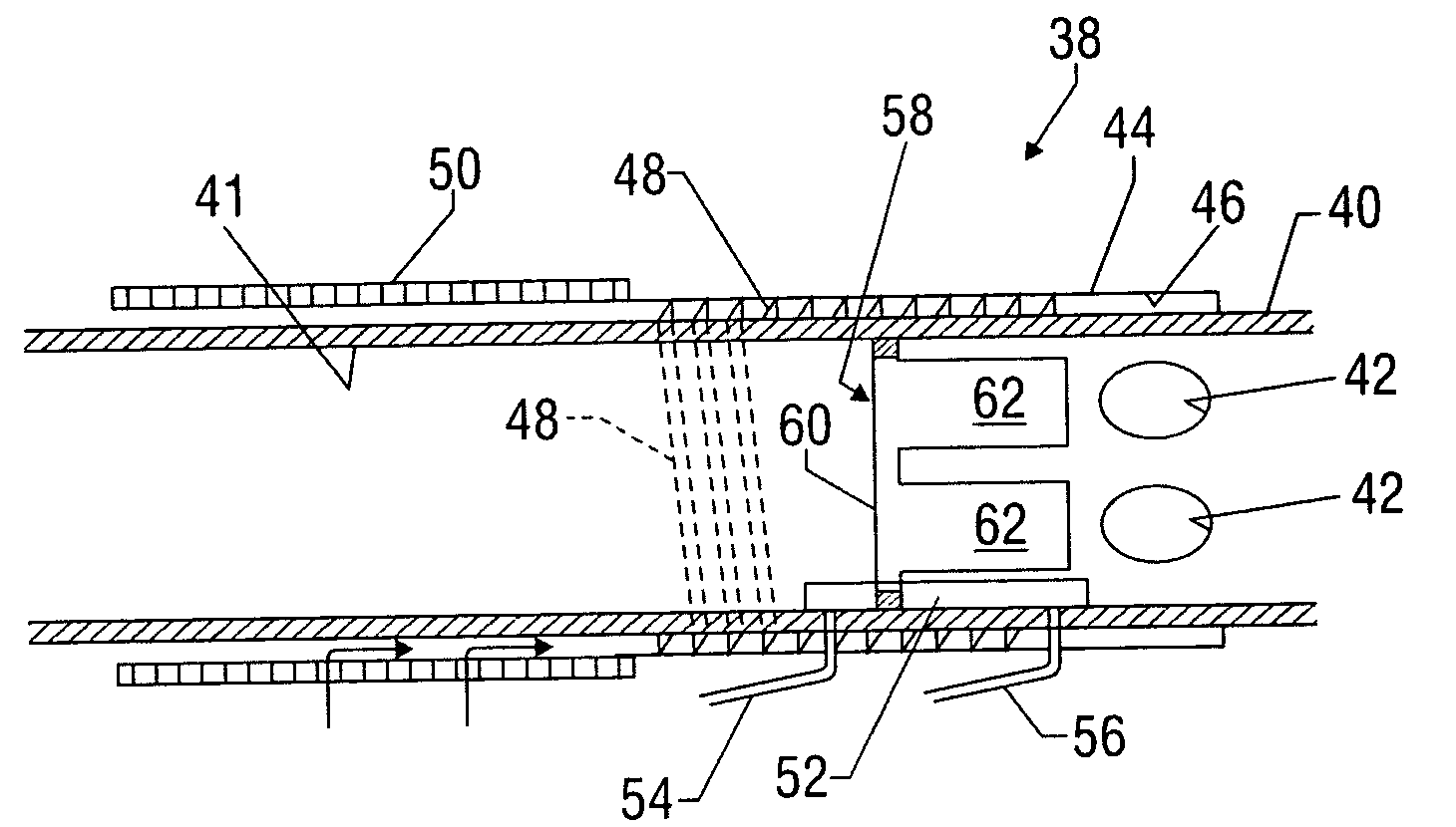
The invention provides a system and method for controlling the inflow of fluid into a production string. It includes a downhole sand screen and inflow control device with a gas or water shut-off feature that can be operated from the surface of the well. The device also has a bypass feature that allows it to be closed or bypassed via shifting of a sleeve. The invention also includes adaptive inflow control devices that can automatically activate the shut-off feature upon detection of a predetermined gas / oil ratio, water / oil ratio, fluid density changes, or operating temperature changes. The invention can restrict or fully shut off fluid flow.

Problems solved by technology

During later stages of production of hydrocarbons from a subterranean production zone, water or gas often enters the production fluid, making production less profitable as the production fluid becomes increasingly diluted.
A particular problem arises in horizontal wellbore sections that pass through a single layer of production fluid.
If fluid enters the production tubing too quickly, it may draw down the production layer, causing nearby water or gas to be drawn down into the production tubing as well.
Inflow control devices currently lack an acceptable means for selectively closing off flow into the production tubing in the event that water and / or gas invades the production layer.
Additionally, current inflow control devices do not have an acceptable mechanism for bypassing the tortuous pathway, so as to increase the production flow rate.

Method used


Image

  • Downhole inflow control device with shut-off feature
  • Downhole inflow control device with shut-off feature
  • Downhole inflow control device with shut-off feature

Examples


Embodiment Construction

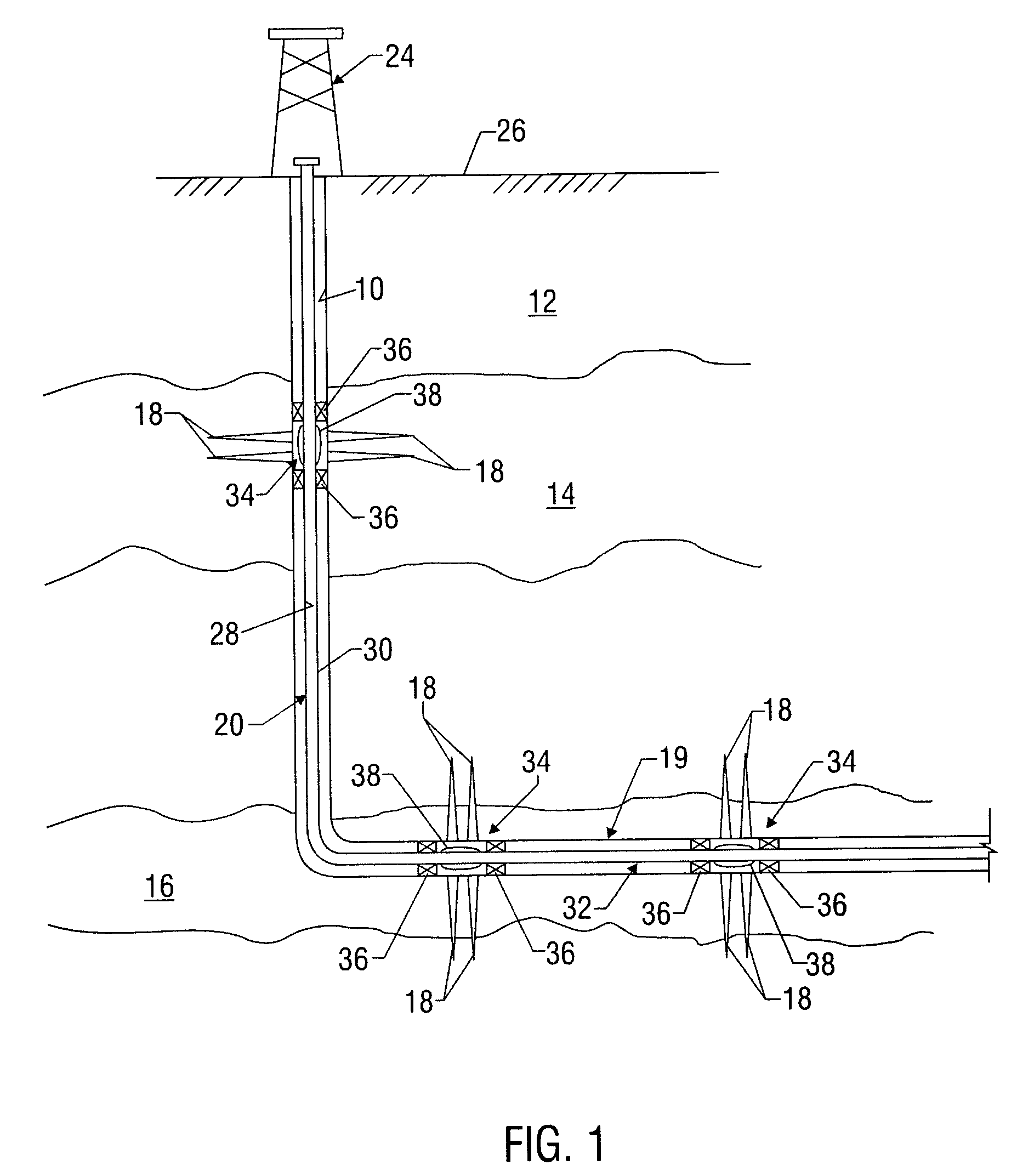
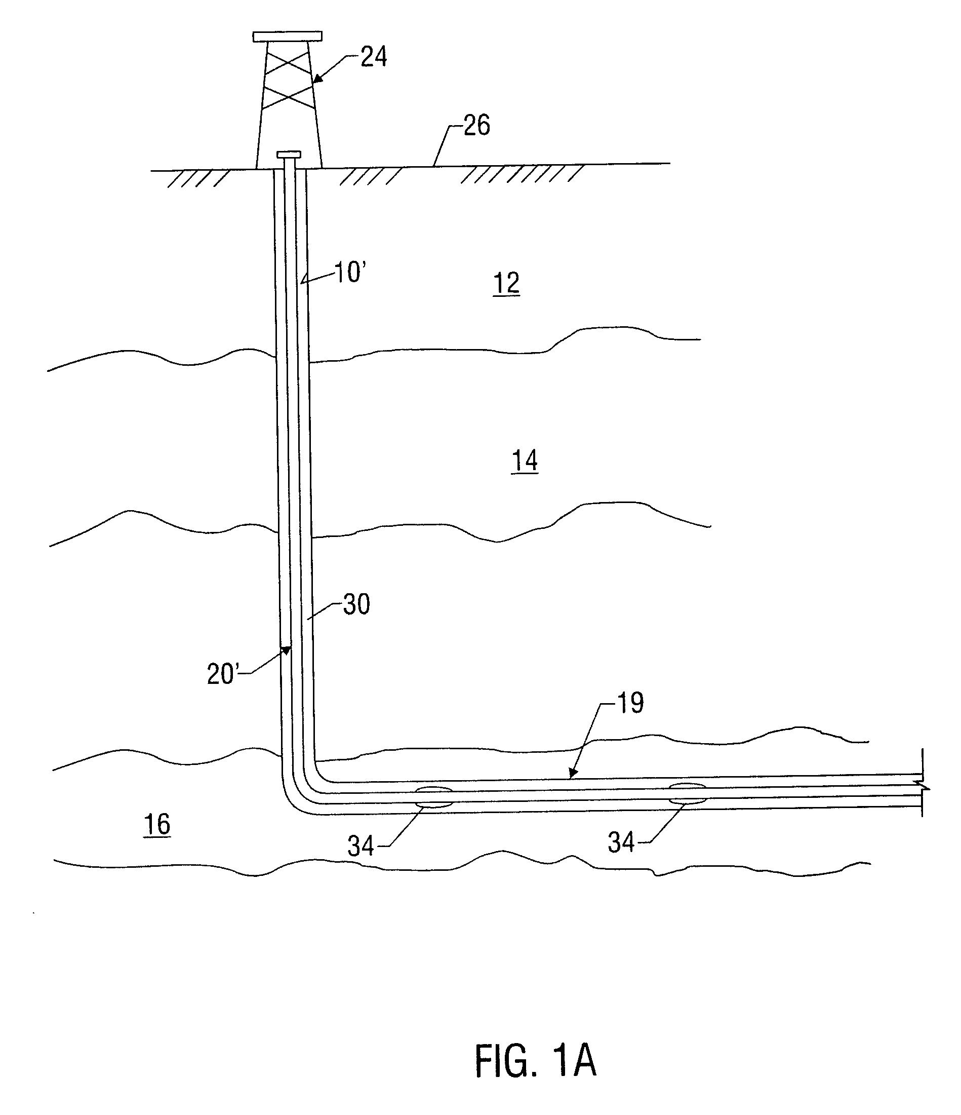
[0033]FIG. 1 depicts an exemplary wellbore 10 that has been drilled through the earth 12 and into a pair of formations 14, 16 from which it is desired to produce hydrocarbons. The wellbore 10 is cased by metal casing, as is known in the art, and a number of perforations 18 penetrate and extend into the formations 14, 16 so that production fluids may flow from the formations 14, 16 into the wellbore 10. The wellbore 10 has a deviated, or substantially horizontal leg 19. The wellbore 10 has a late-stage production assembly, generally indicated at 20, disposed therein by a tubing string 22 that extends downwardly from a wellhead 24 at the surface 26 of the wellbore 10. The production assembly 20 defines an internal axial flowbore 28 along its length. An annulus 30 is defined between the production assembly 20 and the wellbore casing. The production assembly 20 has a deviated, generally horizontal portion 32 that extends along the deviated leg 19 of the wellbore 10. At selected points a...


PUM


Abstract

A system and method for controlling inflow of fluid into a production string. In aspects, the invention provides a downhole sand screen and inflow control device with a gas or water shut-off feature that can be operated mechanically or hydraulically from the surface of the well. The device also preferably includes a bypass feature that allows the inflow control device to be closed or bypassed via shifting of a sleeve. In embodiments, the flow control device can be adaptive to changes in wellbore conditions such as chemical make-up, fluid density and temperature. Exemplary adaptive inflow control devices include devices configured to control flow in response to changes in gas / oil ratio, water / oil ratio, fluid density and / or the operating temperature of the inflow control device. In other aspects of the present invention, inflow control devices are utilized to control the flow of commingled fluids drained via two or more wellbores.

Description

CROSS-REFERENCE TO RELATED APPLICATIONS [0001] This application takes priority from U.S. Provisional Application Ser. No. 60 / 592,496 filed on Jul. 30, 2004.BACKGROUND OF THE INVENTION [0002] 1. Field of the Invention [0003] The invention relates generally to systems and methods for selective control of fluid flow into a production string in a wellbore. In particular aspects, the invention relates to devices and methods for actuating flow control valves in response to increased water or gas content in the production fluids obtained from particular production zones within a wellbore. In other aspects, the invention relates to systems and methods for monitoring flow rate or flow density at completion points and adjusting the flow rate at individual production points in response thereto. [0004] 2. Description of the Related Art [0005] During later stages of production of hydrocarbons from a subterranean production zone, water or gas often enters the production fluid, making production l...

Claims


Application Information

Patent Timeline
Patent Type & Authority Applications(United States)
IPC IPC(8): E21B34/10
CPCE21B34/08E21B34/10E21B43/12E21B43/14E21B2200/02
Inventor HENRIKSEN, KNUTCOULL, CRAIGHELSENGREEN, ERIK
Owner BAKER HUGHES INC
Learn More