
All-directional camera viewfinder angle adjusting mechanism

Inactive Publication Date: 2006-05-25
LOUIS INT PATENT OFFICE
View PDF6 Cites 66 Cited by
  • Summary
  • Abstract
  • Description
  • Claims
  • Application Information

AI Technical Summary

Benefits of technology

[0007] It is therefore an objective of this invention to provide an all-directional camera viewfinder angle adjusting mechanism for use with a Web camera or the like to allow the Web camera to be rotatable in full-angle 360° range both horizontally or vertically, so as to allow the user to aim the viewfinder angle of the Web camera arbitrarily at any desired directions.
[0008] The all-directional camera viewfinder angle adjusting mechanism according to the invention is designed for use in conjunction with a photographic device, such as a Web camera, for the purpose of allowing the user to arbitrarily adjust the viewfinder angle of the photographic device to any directions within 360° full-angle range both horizontally and vertically so as to aim the photographic device precisely at the target object that is to be photographed.
[0009] Compared to prior art, the all-directional camera viewfinder angle adjusting mechanism of the invention allows the user to precisely adjust the viewfinder angle of a Web camera to any desired directions so that there will be no dead spots in the scene that is to be photographed, and is therefore more advantageous to use than the prior art.

Problems solved by technology

One drawback to present Web cameras on the market, however, is that they are typically capable of allowing the user to adjust the viewfinder angle horizontally in full-angle range (i.e., 360°), but only a limited angular range (typically only about 30°) in the vertical direction.
This limitation restricts the user from arbitrarily adjusting the viewfinder angle of the Web camera to any desired directions, thus undesirably resulting in some dead spots in the scene that is to be photographed.

Method used


Image

  • All-directional camera viewfinder angle adjusting mechanism
  • All-directional camera viewfinder angle adjusting mechanism
  • All-directional camera viewfinder angle adjusting mechanism

Examples


Embodiment Construction

[0015] The all-directional camera viewfinder angle adjusting mechanism according to the invention is disclosed in full details by way of preferred embodiments in the following with reference to the accompanying drawings.

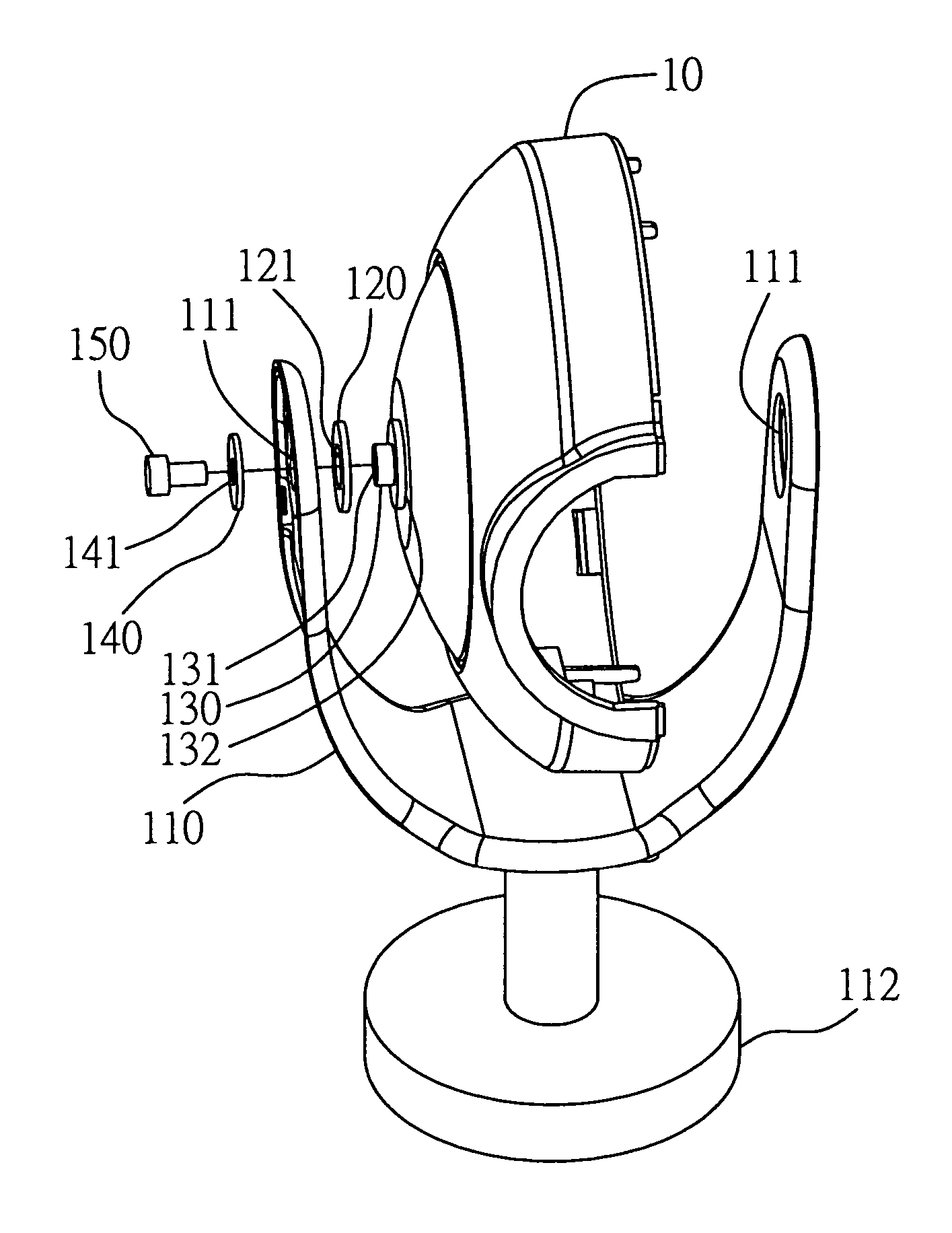
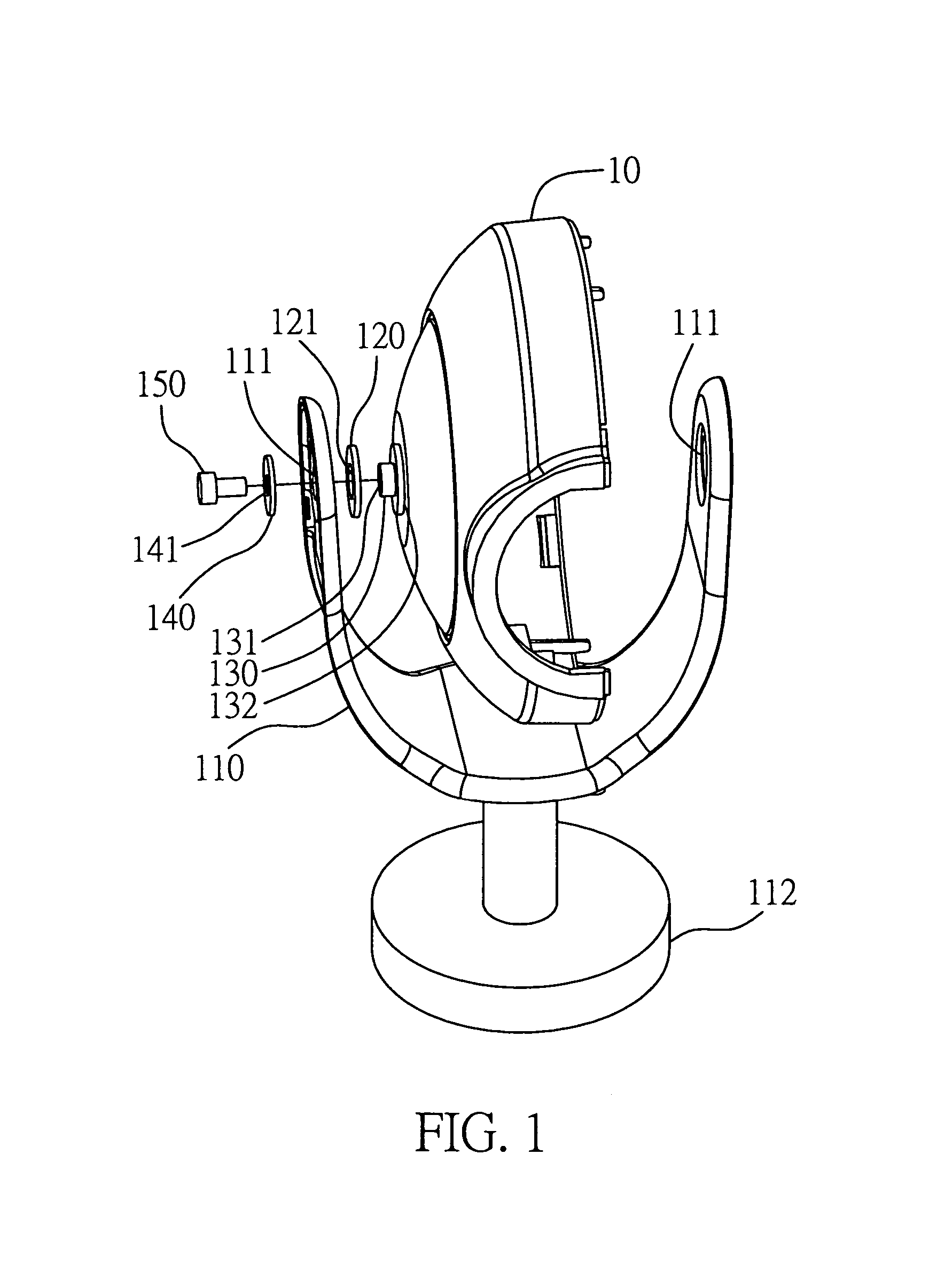
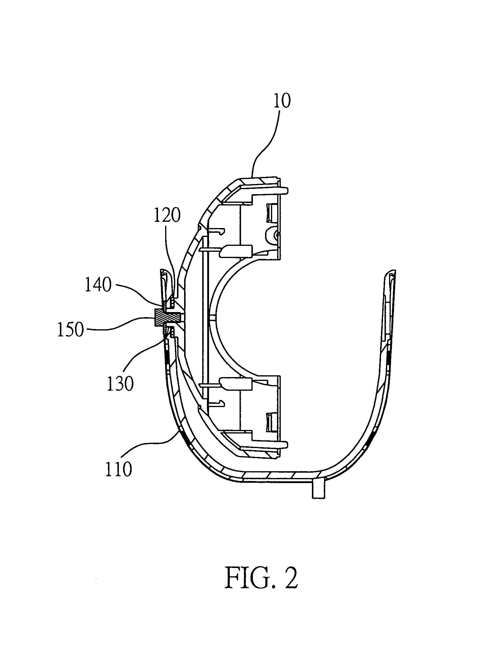
[0016]FIG. 1 is a schematic diagram showing an exploded perspective view of the all-directional camera viewfinder angle adjusting mechanism of the invention and a photographic device 10, such as a Web camera (note that in FIG. 1, only a half part of the Web camera is shown). In practical application, for instance, the photographic device 10 can be either a Web camera or a security monitor camera. Functionally, the all-directional camera viewfinder angle adjusting mechanism of the invention is designed for the purpose of allowing the user to arbitrarily adjust the viewfinder angle of the photographic device 10, either vertically or horizontally, to any directions so as to aim the photographic device 10 precisely at the target object that is to be photographed.

[0017]...


PUM


Abstract

An all-directional camera viewfinder angle adjusting mechanism is proposed, which is designed for use in conjunction with a photographic device for the purpose of allowing the user to arbitrarily adjust the viewfinder angle of the photographic device to any directions within 360° full-angle range both horizontally and vertically so as to aim the photographic device precisely at the target object that is to be photographed. Compared to prior art, the proposed all-directional camera viewfinder angle adjusting mechanism allows the user to precisely adjust the viewfinder angle of a Web camera to any desired directions so that there will be no dead spots in the scene that is to be photographed, and is therefore more advantageous to use than prior art.

Description

BACKGROUND OF THE INVENTION [0001] 1. Field of the Invention [0002] This invention relates to camera technology, and more particularly, to an all-directional camera viewfinder angle adjusting mechanism which is designed for use in conjunction with a photographic device, such as a Web camera, for the purpose of allowing the user to arbitrarily adjust the Web camera's viewfinder angle to any desired directions so as to aim the Web camera's viewfinder precisely at the target object that is to be photographed. [0003] 2. Description of Related Art [0004] Web camera is a digital image capturing device that is capable of capturing still or motion images (i.e., video images) in digital form and is capable of being linked to a computer platform, such as a desktop computer, a notebook computer, a network workstation, or the like, for processing and transferring the captured images via a network system, such as an LAN (Local Area Network) system or the Internet, to a remote computer platform, ...

Claims


Application Information

Patent Timeline
IPC IPC(8): H04N5/225G03B17/00
CPCH04N5/2251H04N23/50
Inventor HO, HSIN-CHIANGTSENG, YI-MIN
Owner LOUIS INT PATENT OFFICE
Learn More