Device for actuating double seat valves

a technology for actuating devices and valves, which is applied in the direction of valve operating means/releasing devices, water supply installation, functional valve types, etc. it can solve the problems of reducing the number of integrated actuators from the manufacturer of double seat valves, the diameter size of the main adjustment device is reduced, and the complexity of the integrated actuator in which only the main adjustment device is activated, so as to reduce the cost and reduce the size of the main adjustment device. , the effect of further reducing th

Inactive Publication Date: 2006-05-25
TUCHENHAGEN GMBH
View PDF2 Cites 16 Cited by
  • Summary
  • Abstract
  • Description
  • Claims
  • Application Information

AI Technical Summary

Benefits of technology

[0017] Since the second actuating piston, not in a necessary but desirable manner, has approximately the same piston cross-section as the first actuating piston in the main adjustment device, the possibility arises through the aforementioned batch function to significantly reduce the size of the main adjustment device relevant to the opening force (this is primarily the diameter), whereby among other things a significant cost reduction takes place. On the other hand from the aforementioned circumstances the possibility arises to actuate the double seat valve without reduction of the size ratio of the actuator even with a low operating pressure of the pressurized medium.
[0033] Overall it has been shown that the proposed device for actuating double seat valves, is realized first of all with a so-called modular actuating concept and secondly, further cost reducing actions were proposed compared to the known so-called integrated actuating leading to a significant reduction of the manufacturing costs which amounts to half of the previous costs.

Problems solved by technology

The significant disadvantages of the integrated actuators arise also from the fact that they are designed for the maximum requirements which are placed on double seat valves of the type under discussion.
Since a large portion of the double seat valves placed in installations in the food and beverage industry are in applications without the possibility or necessity of seat cleaning, because only mixing efficiency is required, integrated actuators in which only the main adjustment device is activated are normally too complex and therefore uneconomical.
In practice these types of applications then fall back on “normal” actuators (standard actuators) for double seat valves, which only accommodate a main adjustment device for the full open position H. Thereby the number of integrated actuators from a manufacturer of double seat valves is reduced, since each double seat valve corresponding to the requested requirements is at best equipped with a suitable actuator for this purpose and thereby results in an uneconomical number of manufactured integrated actuators as the case may be.

Method used


Image

  • Device for actuating double seat valves
  • Device for actuating double seat valves
  • Device for actuating double seat valves

Examples


Embodiment Construction

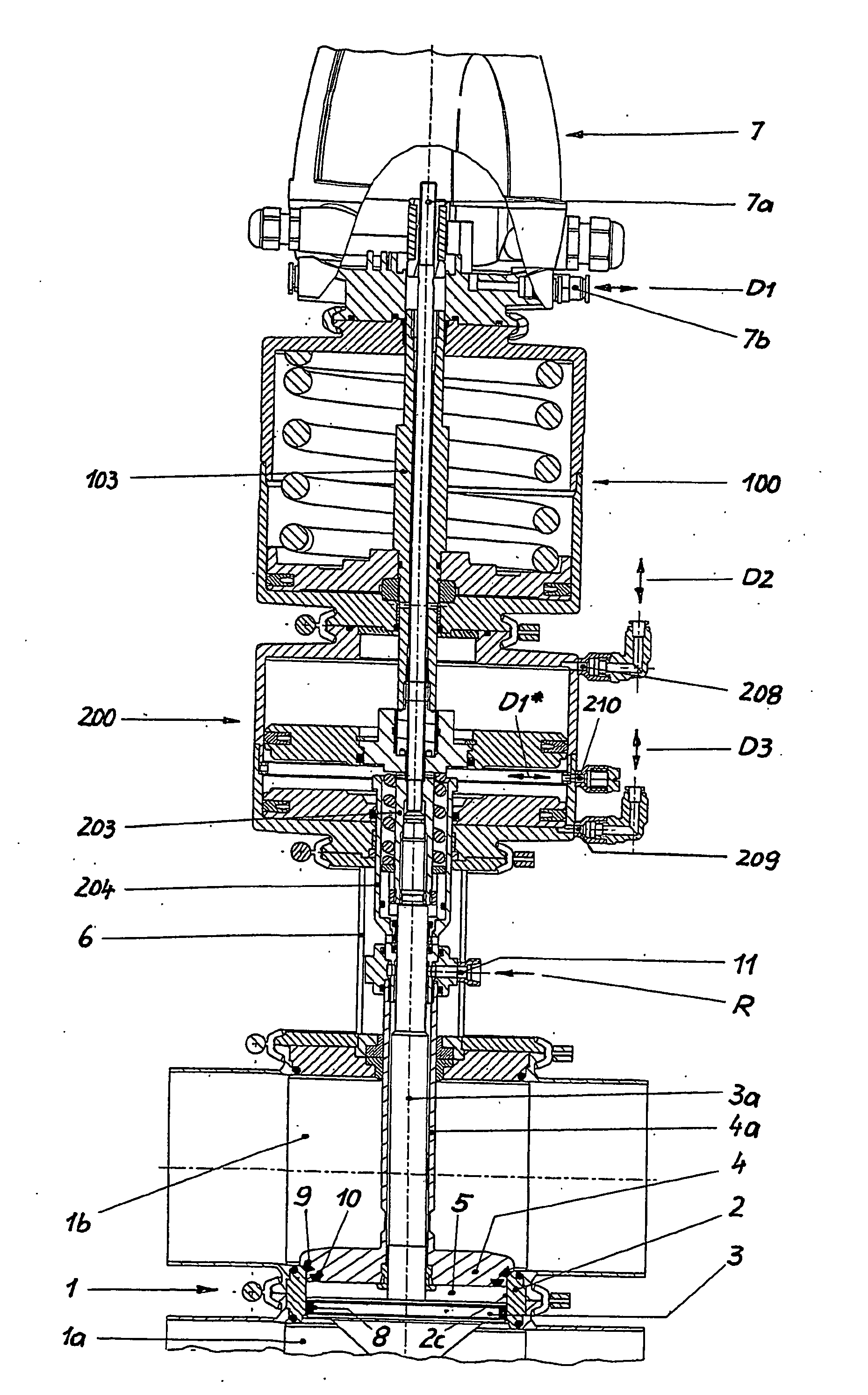
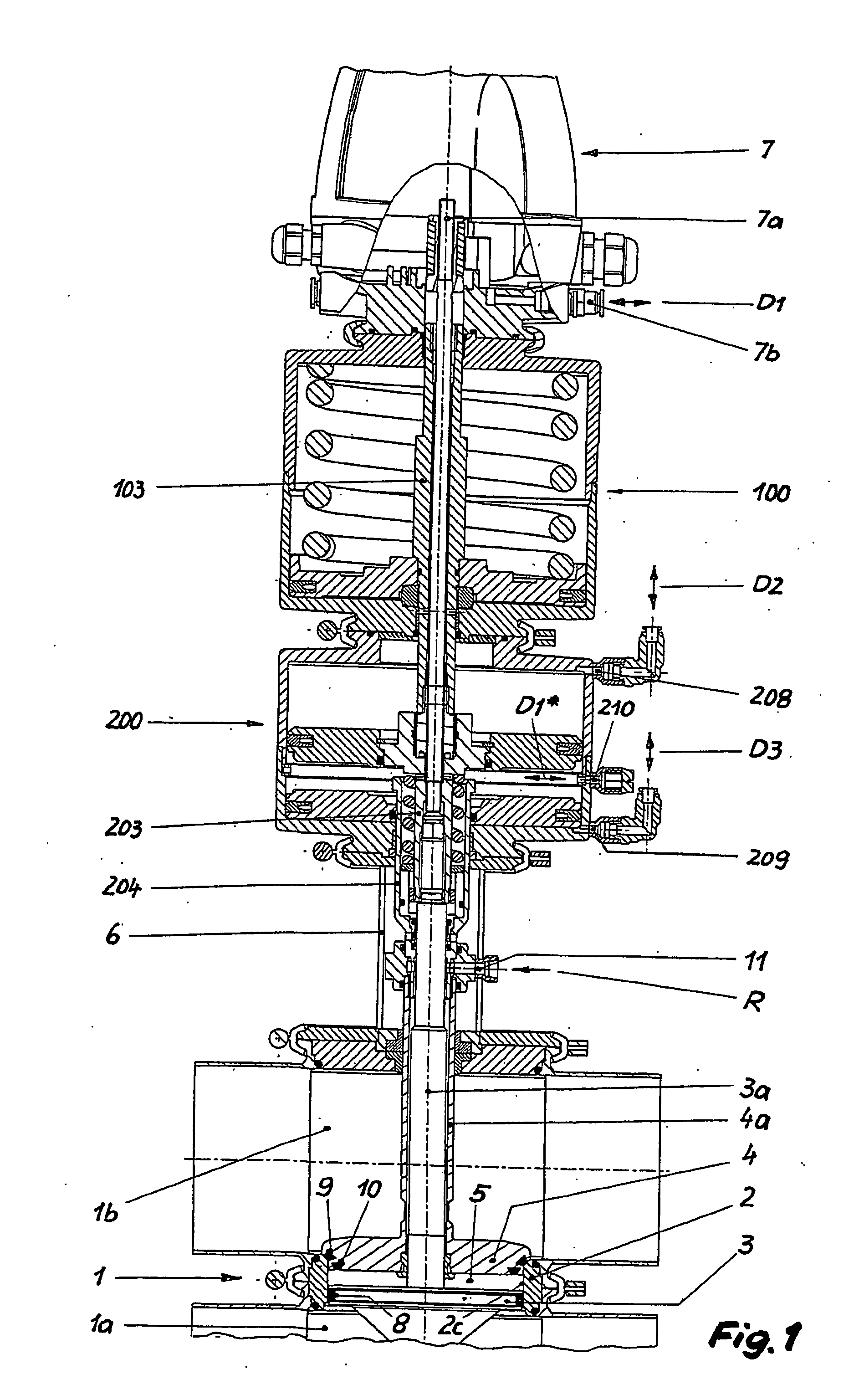
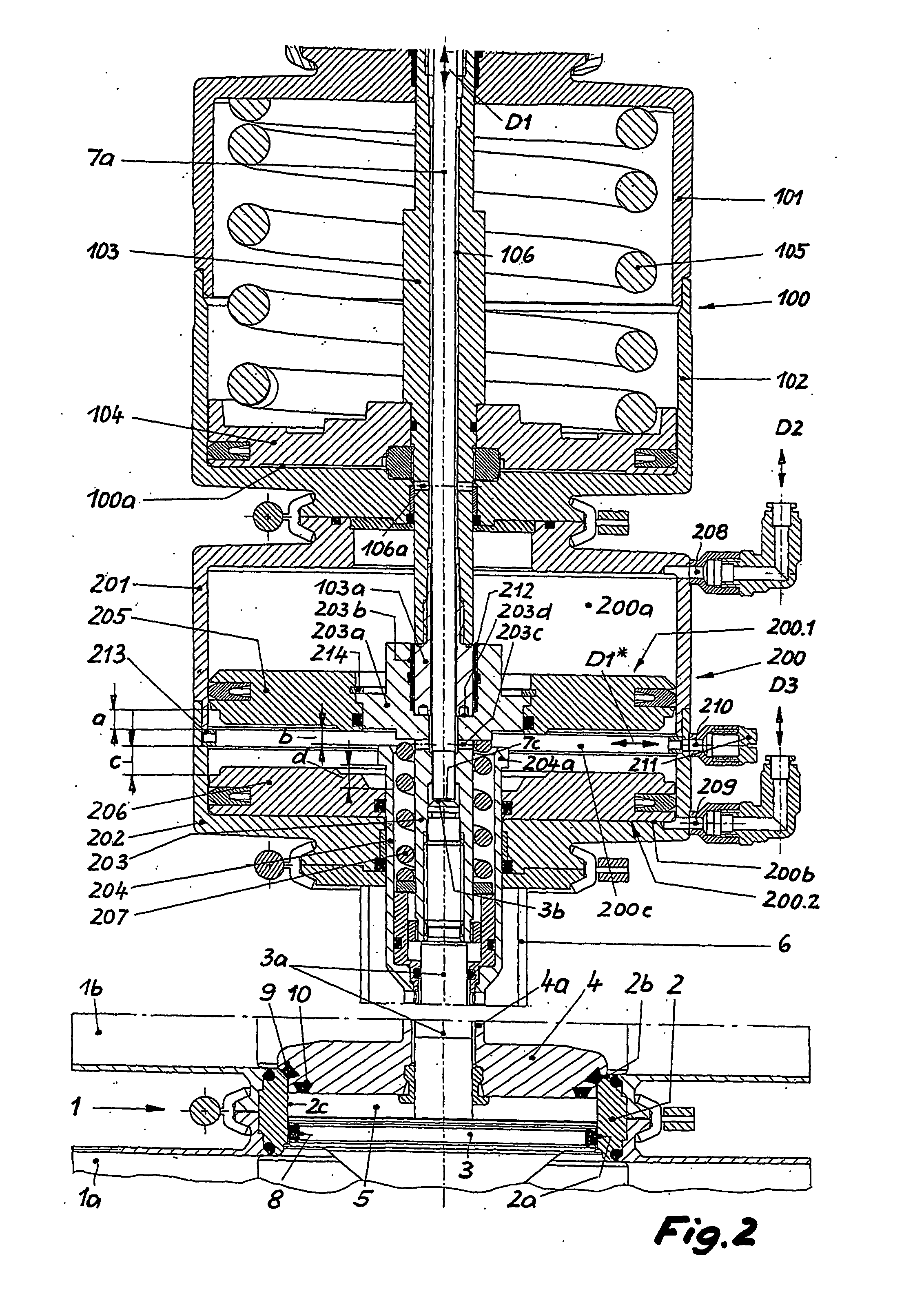
[0042] The proposed device 100, 200 (FIG. 1) is used for actuating a double seat valve, that is essentially made up of a valve housing 1 with a first and a second valve housing member 1a or 1b, two closing elements 2 and 4 which move independently to each other using the arranged adjustment rods 3a or 4a in each case, a seat ring 2 which makes a connection between the valve housing members 1a, 1b using its inner connection orifice 2c, a lantern housing 6 connecting the second valve housing member 1b with the device 100, 200, as well as a control device 7, whereby the latter is arranged on the side of the device 100, 200 opposite to the double seat valve.

[0043] The independently actuated, first closing element 3 designed as a sliding piston is equipped on the circumference with a first seat seal 8 working exclusively in the radial direction, which is attached to a first seat surface 2a (FIG. 2), which is formed from the cylindrical surface in the seat ring 2 which borders the connec...


PUM


Abstract

The invention relates to a device for actuating double seat valves, which are especially suitable for the food and beverage industry and which have an independently actuated first closing element (3), which is designed as a sliding piston and a fully dependent on this actuated second closing element (4), which is designed as a seat disc, whereby the actuator (100, 200) produces at all times using a main adjustment device (100) for the fully open position (H) as well as, for the case of maximum requirements, the respective individual adjustment devices (200; 200.1, 200.2) which are assigned to the closing elements (3, 4) for generation of the partially open positions (T1, T2) acting in opposite directions for the seat cleaning of the closing elements (3, 4). The object of the invention is to design a device according to this generic type in such a manner that it is constructed as simply as possible and is easily and economically adjustable to the various requirements which are put onto a double seat valve of the type in discussion (only full opening stroke or full opening stroke as well as seat cleaning partial strokes). This is thus achieved in that the individual adjustment devices (200; 200.1, 200.2) are designed stand-alone and are additively inserted between the main adjustment device (100) and a valve housing (1), that the third working piston (206;206 / 206.1) is positioned able to be moved axially on the second control rod (4a, 204) which is designed as a hollow rod, and encloses the first control rod (3a, 203) and is able to be brought in the direction of the second partially open position (T2) in a clamped connection, that the second actuating piston (205) is tightly connected on one side with the first control rod (3a, 203) which adjusts the first closing element (3), that it is otherwise directly or indirectly positioned able to be moved axially on a first actuator stem (103) of the main adjustment device (100) and is able to be brought with this in the direction of the fully open position (H) in a clamping connection, and that it is able to be loaded with pressurizing medium on each of its two piston surfaces (FIG. 2).

Description

TECHNICAL FIELD [0001] The invention relates to a device for actuating double seat valves, especially for the food and beverage industry, according to the preamble of Claim 1. PRIOR ART [0002] A device according to this generic type is known from EP 0 868 619 B1. The device diagrammed in FIG. 6 and explained briefly in the attached description is in fact not subject matter of the patent claims of this publication, however the features disclosed prove how through simple modification to the protected actuating device 1 (reference numbers of the figures therein) a double seat valve can be activated, whose independently actuated first closing element 4 is designed as a sliding piston with radial sealant and whose dependently actuated second closing element 5 is designed as a seat disc. In this closing element configuration the partially open position T1 of the first closing element 4 is completed in the opposite direction to the opening stroke H, which is directed upwards relative to th...

Claims


Application Information

Patent Timeline
IPC IPC(8): F16K31/143F16K1/44F16K31/122
CPCF16K1/446Y10T137/8803Y10T137/4259Y10T137/88046Y10T137/5762Y10T137/88038F16K31/1225
Inventor BURMESTER, JENS
Owner TUCHENHAGEN GMBH
Why Eureka
Try Eureka