
Portable terminal

a terminal and portability technology, applied in the field of boot processing, can solve the problems of not being able to disclose the response to errors in the nand flash memory, and not being able to disclose the product manufacturing testing of the device, so as to improve the reliability in the event of an error in the system memory

Inactive Publication Date: 2006-05-18
KK TOSHIBA
View PDF16 Cites 25 Cited by
  • Summary
  • Abstract
  • Description
  • Claims
  • Application Information

AI Technical Summary

Benefits of technology

[0013] According to the present invention, image display matched to the progress of execution of the initialization function in a small and inexpensive device such as a portable terminal is possible. Furthermore, while using inexpensive NAND flash memories, it is possible to improve reliability in the event of an error with limited NAND flash memory without providing redundancy.
[0015] Furthermore, after loading from the NAND flash memory to the system memory, reliability in the event of an error in the system memory may be improved.

Problems solved by technology

Furthermore, response to errors in the NAND flash memory is not disclosed.
Furthermore, nothing related to manufacturing testing of the device is disclosed.

Method used


Image

  • Portable terminal
  • Portable terminal
  • Portable terminal

Examples


first embodiment

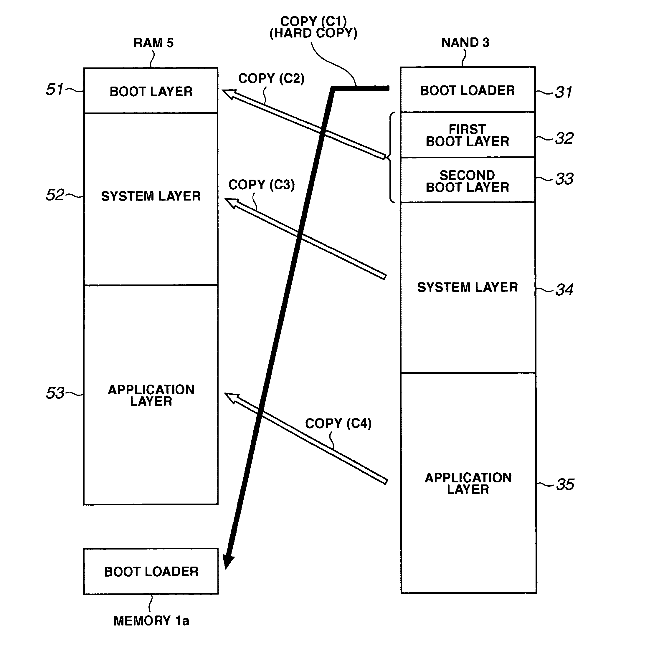
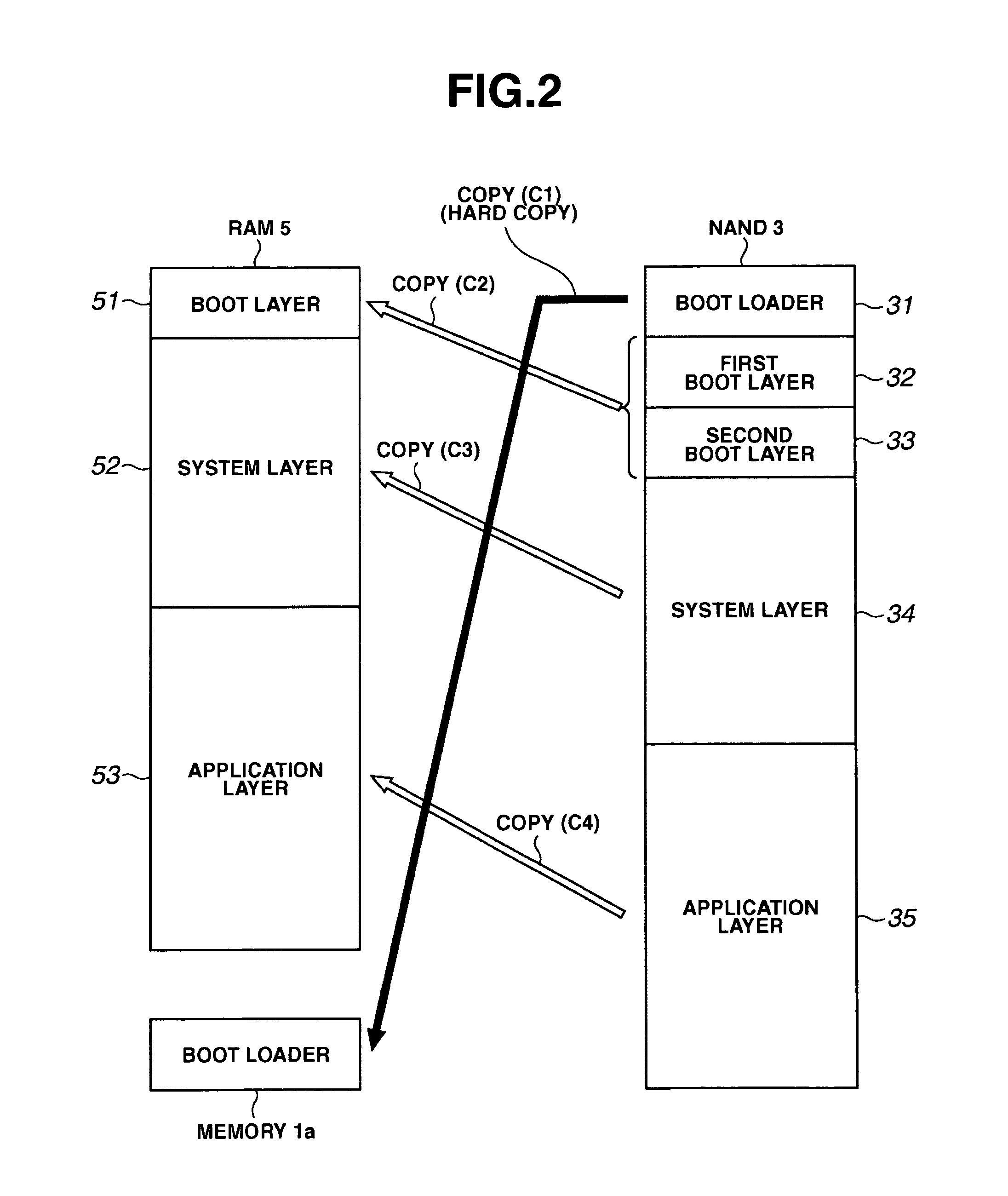
[0031]FIG. 2 is a diagram describing the boot mechanism at power on for a portable terminal according to the first embodiment of the present invention. Boot is a mechanism for loading (copying) programs from the program storage area to the system memory and the like, and the CPU initializing these programs in system memory, at power on.

[0032] The boot loader 31, the first boot layer 32, the second boot layer 33, the system layer 34, and the application layer 35 programs are stored in the NAND flash memory 3 beforehand. The boot loader 31 (that is to say, the loader of the boot layer) is a program to load (copy C2) the first boot layer 32 or the second boot layer 33 into the boot layer 51 of the RAM 5.

[0033] The content of the first boot layer 32 and the content of the second boot layer 33 are the same, two boot layers being provided for the purpose of backup. This program has a function to initialize screen display and the like at startup as required for initialization following p...

second embodiment

[0053]FIG. 5 is a general flowchart for a portable terminal according to the second embodiment of the present invention at boot. In the present embodiment, the application layer 35 in the NAND flash memory 3 (FIG. 2) is further divided into a plurality of application layers, each application layer being copied to the RAM 5, and executed in the RAM 5. The part of the general flowchart (1 / 2) (FIG. 3) at boot in the first embodiment describes the same operation and the part of the general flowchart (2 / 2) (FIG. 4) subsequently executed differs. This is described using FIG. 5.

[0054] When copying of the system layer 34 to the RAM 5 is complete, execution of the system layer in the RAM begins (step S400). The CPU 1 executes the OS (step S401) in accordance with the content of the system layer 52 in the RAM 5. At this time, the hardware functions of the portable terminal are all operable. Manufacturing testing (steps S402, S70) is the same as for the first embodiment (FIG. 4), and a descri...


PUM


Abstract

Screen display matched to the progress of execution of the initialization function in small and inexpensive devices such as a portable terminal is performed. Furthermore, reliability in the event of an error is improved without providing excessive redundancy and with limited capacity in a NAND flash memory storing programs. A first boot layer and a second boot layer of the same content are stored in the NAND flash memory. The boot layer free from errors is copied (C2) to a RAM (step S21), and a boot layer program is executed in the RAM (step S30). A simple logo and the like comprising characters is then displayed (first screen display) (step S32). Next, a system layer program is executed in the RAM (step S40). A screen (second screen display) is then displayed by switching between a plurality of images (step S44).

Description

CROSS-REFERENCE TO RELATED APPLICATIONS [0001] This application is based upon and claims the benefit of priority from the prior Japanese Patent application No. 2004-334491, filed on Nov. 18, 2004; the entire contents of which are incorporated herein by reference. BACKGROUND OF THE INVENTION [0002] 1. Field of the Invention [0003] The present invention relates to boot processing, being processing at memory system startup, in a portable terminal, and more particularly to image display at boot, improved reliability, and improved efficiency of manufacturing testing. [0004] 2. Description of the Related Art Related Art 1 [0005] For example, as disclosed in Japanese Patent Application Laid-open No. 2003-271391, a boot system using a NAND flash memory, and a related method, are known. [0006] On p 4 of the ‘Prior Art’, and in FIG. 1, of the Japanese Patent Application Laid-open No. 2003-271391, it is disclosed that the BIOS is a program executing an initialization function including a disp...

Claims


Application Information

Patent Timeline
IPC IPC(8): G06F9/24
CPCG06F9/4401
Inventor KOUNO, TAKASHISHISHINO, SHINICHIABE, YASUHIKOTOMIOKA, MUNEHISAINOUE, SAKAE
Owner KK TOSHIBA
Learn More