
Method and apparatus for spatially coordinating, storing and manipulating computer aided design drawings

a computer aided design and spatial coordination technology, applied in the field of methods and apparatus for spatially coordinating computer aided design (cad) drawings for storage and manipulation, can solve the problems of not providing a method for spatially locating cad drawing files, autocad does not provide a method for systematically relating all the drawing files of projects together spatially in working space, etc., to eliminate one of the most time-consuming, frustrating and difficult aspects. , the effect of saving tim

Inactive Publication Date: 2006-05-11
BELL ROBERT A
View PDF35 Cites 17 Cited by
  • Summary
  • Abstract
  • Description
  • Claims
  • Application Information

AI Technical Summary

Benefits of technology

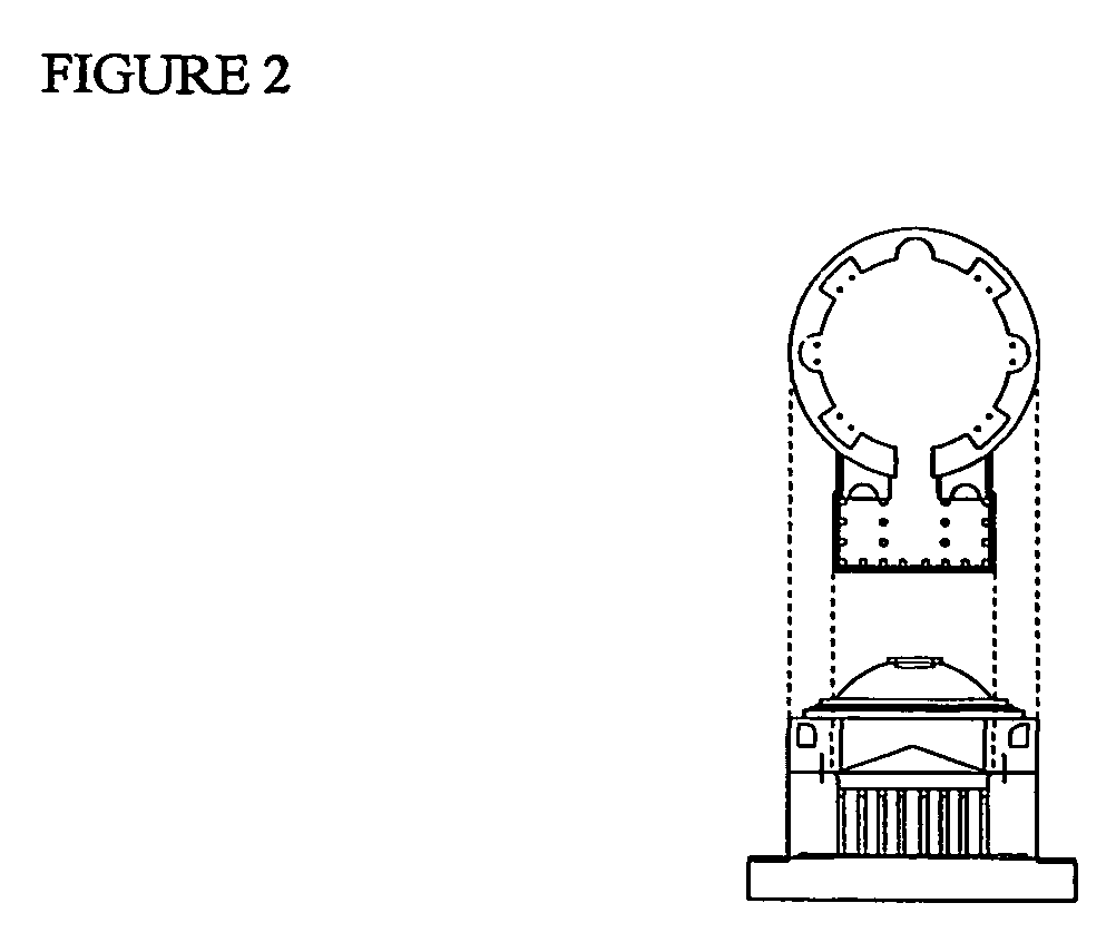
[0014] The above-identified limitations in the art are overcome by providing a spatial coordination system that uses existing CAD software functions to create an independent coordinating file known as the Master Dimensional Plan (MDP) File. Elevations, sections and details that are orthographically projected from coordinated plan files are mapped to the MDP File by using similar parallel shapes to coordinate points of elevations on all z axis drawings simultaneously. In addition, data such as centerlines, site or floor elevations are also located on the MDP file, thus allowing this information to exist in one and only one place in a set of drawings or a contract (architectural) document.
[0015] Software macros are also used to provide switching icons that provide an intuitive method for the user to move from one CAD file to another related CAD file in a CAD drawing system. The resulting method is similar to using icons in a window display versus using DOS language commands except that the icons of the invention describe the drawing view as opposed to the launch of a program function.
[0016] This iconic method of switching files in accordance with the invention is based on using already understood standard graphic architectural symbols such as section cut symbols, elevation symbols, floor level symbols, etc. These icons already are used to inform those knowledgeable in architecture where to look for more specific information about a project. With the use of these symbols as icons that function as macro switches in the CAD drawing program, the historical method of organization and understanding architectural information may be integrated with an electronic method of organizing CAD architectural drawing files in accordance with the invention to provide the technical effect of overcoming the afore-mentioned limitations in the prior art.
[0017] The present invention provides a spatially coordinated system of displaying all the CAD drawings of the various parts of an object. As will be explained in detail below, such a display consists of various CAD files such as plans, Master Coordinating files, sections, elevations, details, etc. Within this display, the method of the present invention includes placing “switch file icons” in the CAD image that will change the active file from one file to another. For example, a “switch file icon” appearing on the plan can be clicked onto to switch the user to another file. For example, if one is viewing the plan, by clicking onto the designated “switch file icon” indicated on the referenced elevation, the active file will be automatically switched to the referenced elevation. This iconic method replaces the “exchange tool” of the “Reference File” toolbox or the Open file toolbox in the conventional CAD drawing software sequence. This switch can take place without going through the process of opening the Reference file tool box, selecting the reference file, selecting the tool selection, and then finally selecting “exchange.” Not only does the technique of the invention save time, but further, and perhaps much more important, the invention allows one to move through various CAD files without understanding or even knowing the nomenclature or directory structure of the files. This technique can eliminate one of the most time consuming, frustrating and difficult aspects of dealing with CAD drawings-understanding the CAD file designation.
[0018] Further, because the method of the invention is graphic and spatial, various existing file systems can be used without adjusting or changing the existing nomenclature of the file system. The importance of this in very large jobs, such as in the Pentagon redesign effort, cannot be overemphasized. The methodology of the invention allows any individual to come onto any job where the CAD coordinating method is used with the CAD locating method of the present invention and began working immediately without learning the filing system.

Problems solved by technology

A problem with existing CAD software systems, such as MicroStation and AutoCAD, is that there is no standard method for spatially locating CAD drawing files relative to each other in working space.
Presently, the U.S. National CAD Standards include a Uniform Drawing System from the Construction Specifications Institute (CSI), CAD Layer Guidelines from the American Institute of Architects (AIA), and Plotting Guidelines from the CAD Geographic Information Systems (GIS) Technical Center and U.S. Coast Guard However, none of these standards provides a method for locating drawing files systematically with respect to each other in working space.
While programs such as AutoCAD allow one to reference any particular point of a drawing back to a point where the X, Y and Z axes are all zero, programs such as AutoCAD do not provide a method for systematically relating all the drawing files of projects together spatially in working space.
For example, in architectural drawings, if floor plan files are not aligned correctly with the structure files, errors or confusion may occur during construction.
Further, if elevation files do not align with the plan files correctly, the openings containing windows may not be properly sized or coordinated with other systems.
However, this approach does not provide a systematic way to coordinate different types of drawing files such as a plan file with elevation files.
The present inventor has further observed that moving between CAD files in conventional CAD systems is difficult because it requires the user to be intimately familiar with the file structure and organization.
This is undesirable, particularly in the case of larger architectural projects where multiple persons access the drawings at different times. A methodology is further desired that makes moving around the architectural views of an object more intuitive.

Method used


Image

  • Method and apparatus for spatially coordinating, storing and manipulating computer aided design drawings
  • Method and apparatus for spatially coordinating, storing and manipulating computer aided design drawings
  • Method and apparatus for spatially coordinating, storing and manipulating computer aided design drawings

Examples


Embodiment Construction

[0052] In the illustrative examples given herein, an architectural design is used as an example of the operation of the spatial coordination and iconic switching techniques of the invention. Of course, the techniques of the invention are not limited to particular types of architectural or object designs but may be used with all types of objects of varying shapes and sizes.

I. System Elements

[0053] Conventional CAD software routines are used in accordance with the invention to create a Master Dimensional Plan (MDP) File that is a separate file upon which all the other files created by the CAD software to represent views of an object are coordinated spatially with each other. The MDP file is the file where organizing dimensions are held to coordinate the dimensions of all other CAD files. Generally speaking, the coordination of plan files “on top of each other” in the same x and y coordinates is universally used in the prior art to organize CAD drawings such that the site plan file h...


PUM


Abstract

A technique and associated software for spatially coordinating, storing, and manipulating computer aided Design (CAD) files with a master dimensional plan (MDP) file (FIG. 1, MPD File, Plan, Electrical, Structural, etc.). The plan, elevation, section, and other related files are coordinated to a single unified spatial layout referenced to the MDP file. Special “tools” are used to design, manipulate and present the information as two-dimensional drawings referenced in the working space to the MDF file. Moving between the CAD drawing files coordinated to the MDP is facilitated by using icons corresponding to standard architectural graphic symbols as switch file icons that switch the user to other view files of the displayed object based on the selected graphic symbol. The technique allows the user who is familiar with standard architectural nomenclature to move through CAD drawing files without needing to know the underlying CAD file structure. The iconic switching technique of the invention may also be used to move among coordinated no-architectural design drawings of industrial items and the like and may also be used independent of the spatial coordinating method as desired.

Description

BACKGROUND OF THE INVENTION [0001] 1. Field of the Invention [0002] The present invention relates to a method and apparatus for spatially coordinating Computer Aided Design (CAD) drawings for storage and manipulation and, more particularly, to a systematic, integrated and accurate method of spatially coordinating, storing and manipulating CAD drawings with a Master Dimensional Plan file. The method of the invention coordinates the location of plans, elevations, and sections in a single unified spatial layout referenced to a Master Dimensional Plan file (referred to herein as the “MDP” file) and uses specific “tools” to design, manipulate and present the information as two-dimensional drawings. Such tools include a method of moving between CAD drawing files using standard architectural graphic symbols as icons without using the file open dialog box, thus allowing the user to move through CAD drawing files without needing to know the underlying CAD file structure. [0003] 2. Descriptio...

Claims


Application Information

Patent Timeline
IPC IPC(8): G06F17/50G06T17/40
CPCG06F17/5004G06F30/13
Inventor BELL, ROBERT A.
Owner BELL ROBERT A
Learn More