
Device and method for treating workpieces

Active Publication Date: 2006-05-11
SCHOTT AG
View PDF15 Cites 50 Cited by
  • Summary
  • Abstract
  • Description
  • Claims
  • Application Information

AI Technical Summary

Benefits of technology

[0018] Therefore, the invention is based on the object of providing an apparatus and a method for the treatment of workpieces which avoid or at least alleviate the drawbacks of known apparatuses and methods.

Problems solved by technology

However, plastic bottles may also have a number of drawbacks compared to glass bottles, for example the plastics used, such as PET, are insufficiently impervious to gases, and consequently the shelf life is shorter, in particular in the case of carbonated drinks, than with glass bottles unless special measures are implemented.
Since drinks bottles are mass-produced products, there is a huge pressure on cost, and consequently there is an ongoing demand for improvements to the coating methods and the apparatuses used for them.
Furthermore, it is assumed that the weight and volume of the pumps prevent them from being mounted on the carousel.
However, this machine has a number of serious drawbacks.
Firstly, the parallel connection of a plurality of pumps is disadvantageous, since multiple tube routing is required.
Furthermore, the stationary arrangement of the pumps is disadvantageous, since the paths from the stations to the pump are relatively long and therefore the pump power is reduced.
However, the use of the rotatable distributor is particularly disadvantageous.
Distributors of this type are extremely difficult to seal and are susceptible to faults caused by foreign bodies.
Furthermore, on account of the fixedly predetermined opening arrangement, the distributor does not allow any variation to the process sequence and therefore this represents an inflexible design.
However, it is not only the method which takes place on the abovementioned apparatus but also the coating of amorphous carbon used which is in need of improvement, since this coating is undesirably colored.
Furthermore, there is a risk of the layer of carbon flaking off in the event of deformation to the bottle.

Method used


Image

  • Device and method for treating workpieces
  • Device and method for treating workpieces
  • Device and method for treating workpieces

Examples


Embodiment Construction

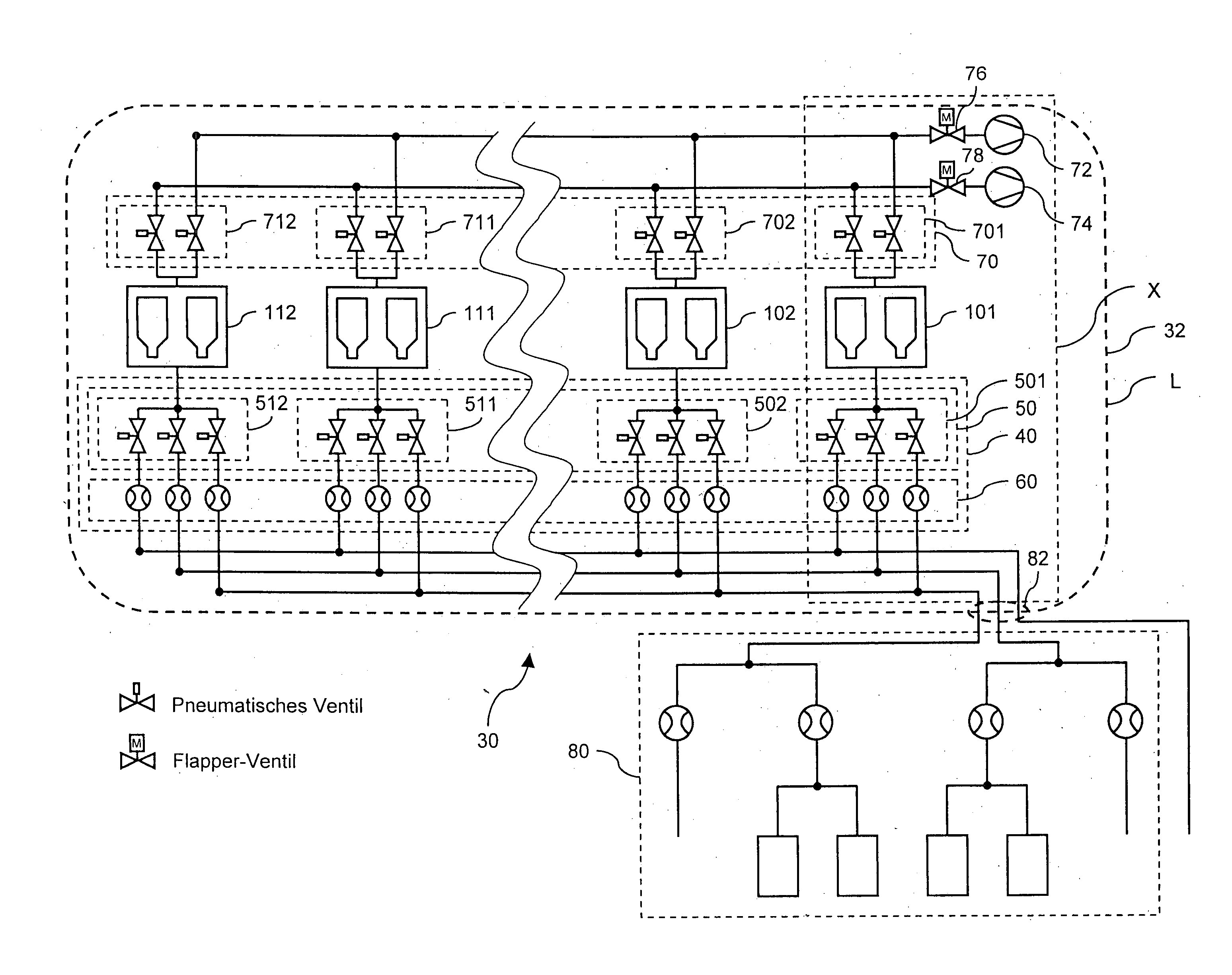
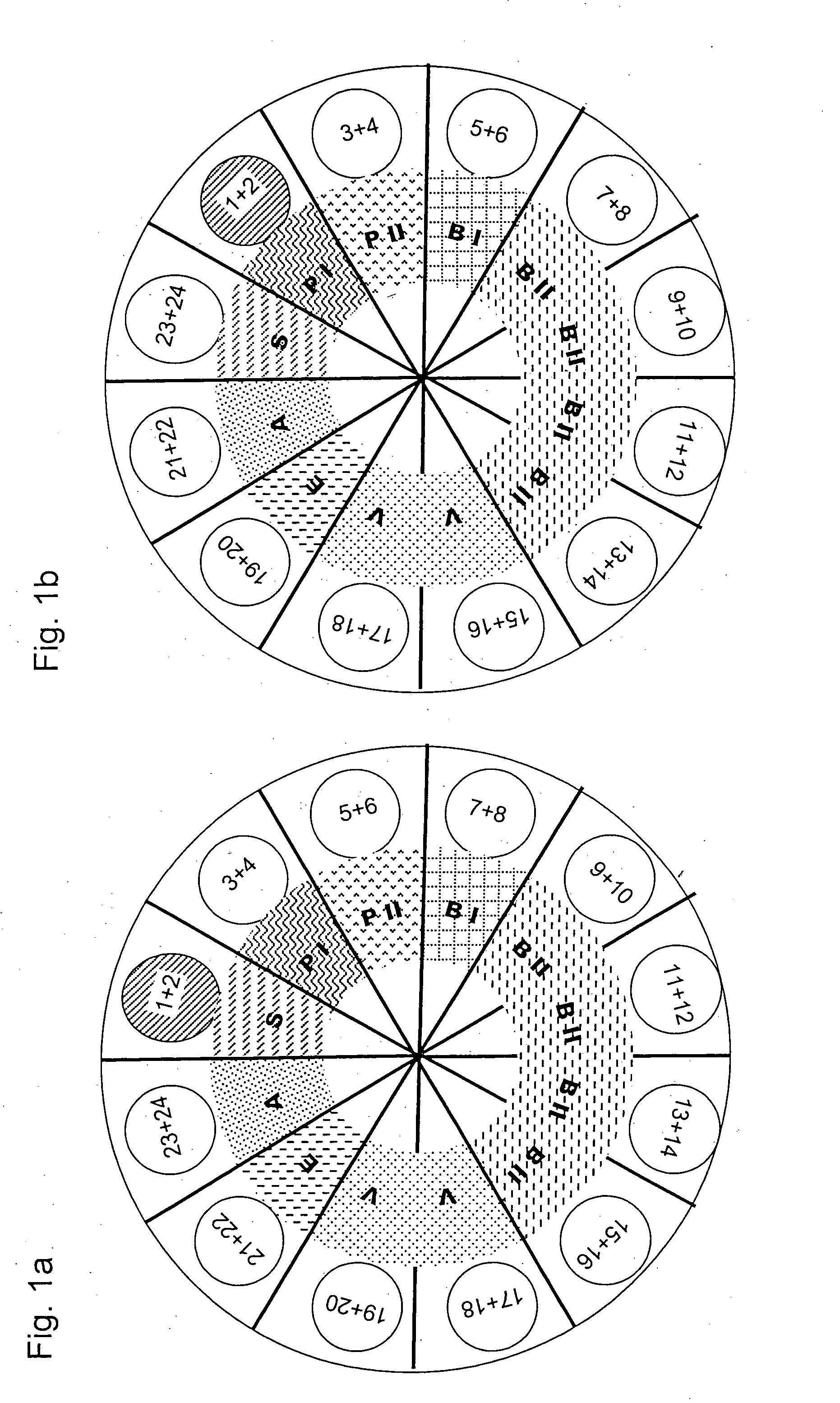
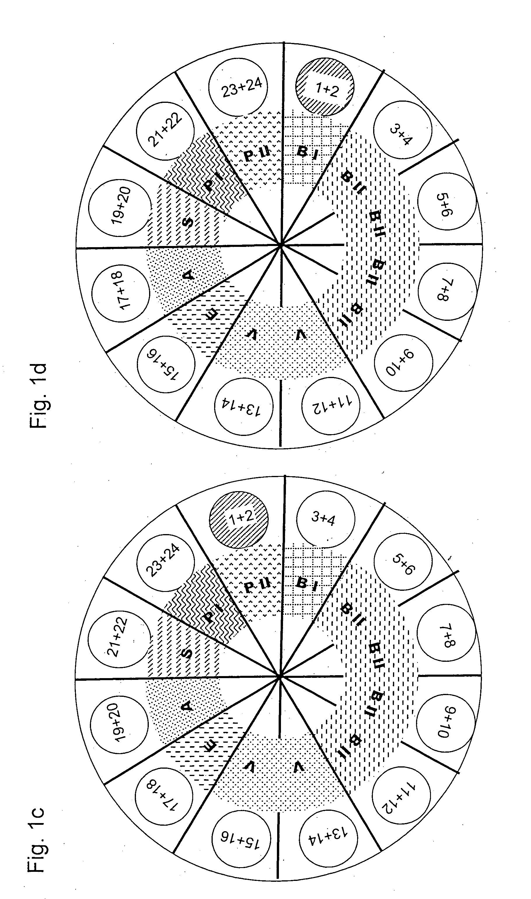
[0108]FIG. 1a diagrammatically depicts a rotor 32 of an apparatus 30 according to the invention.

[0109] On the rotor 32 there are twelve treatment devices, represented by the circles. Each treatment device comprises two treatment stations or reactors, which are numbered consecutively from 1 to 24. The treatment devices are distributed uniformly, i.e. are arranged at angular intervals of 30°.

[0110] Furthermore, eight process phases are illustrated, namely: [0111] a starting phase S, [0112] a first pumping phase PI, [0113] a second pumping phase PII, [0114] a first coating phase BI, [0115] a second coating phase BII, [0116] a vent phase V, [0117] an end phase E, and [0118] an auxiliary phase A.

[0119]FIG. 1a shows a time state in which the treatment stations 1 and 2 are in the starting phase S. This also predetermines the respective process phases or process steps of the other treatment devices or treatment stations. The treatment stations 3 and 4 are in the first pumping phase PI, t...


PUM

PropertyMeasurementUnit
Timeaaaaaaaaaa
Timeaaaaaaaaaa
Pressureaaaaaaaaaa

Abstract

An apparatus and a method for the coating of hollow bodies, in particular for the internal coating of plastic drinks bottles by means of a PICVD is provided. The method ensures a flexible process sequence, a high throughput, an improved supply of fluid and a high-quality coating. The rotary apparatus includes a treatment device with double reactors for receiving in each case at least one workpiece, a fluid supply apparatus and at least one fluid control device, which can be used to control the supply of fluid to the treatment device. It is preferable for the vacuum pumps to be arranged on the rotor such that they rotate therewith.

Description

FIELD OF THE INVENTION [0001] The invention relates to an apparatus and a method for the treatment of workpieces with fluids in general and for the coating of hollow bodies in particular. BACKGROUND OF THE INVENTION [0002] Plastics, in particular transparent plastics, are becoming increasingly important and in many sectors are displacing glass as the preferred material. [0003] One example includes drinks bottles, which a few years ago were made almost exclusively from glass but nowadays are already to a large extent being made from PET. The reason for this is the huge weight saving. [0004] However, plastic bottles may also have a number of drawbacks compared to glass bottles, for example the plastics used, such as PET, are insufficiently impervious to gases, and consequently the shelf life is shorter, in particular in the case of carbonated drinks, than with glass bottles unless special measures are implemented. [0005] For this reason, plastic bottles are internally provided with a ...

Claims


Application Information

Patent Timeline
IPC IPC(8): C23C16/00B05D1/02H05H1/24B05D7/24B08B7/00B29C49/42B65D23/02C03C17/00C08J9/00C23C16/02C23C16/04C23C16/40C23C16/455C23C16/54
CPCB05D1/62B08B7/00B29C49/421B29C2791/001B65D23/02B65G2201/0244C08J9/0004C08J2300/14C23C16/029C23C16/045C23C16/402C23C16/54H01J37/32733B29C2049/4221B29C49/42105B29C49/42069B29C49/42073B29C49/42075B29C49/42095B29C49/42115B29C49/42384B29C49/6835
Inventor BEHLE, STEPHENLUTTRINGHAUS-HENKEL, ANDREASARNOLD, GREGORBICKER, MATTHIASKLEIN, JURGEN
Owner SCHOTT AG
Learn More