
Apparatus and method for performing dynamic capacitance compensation (DCC) in liquid crystal display (LCD)

a liquid crystal display and capacitance compensation technology, applied in the field of dynamic capacitance compensation (dcc) of liquid crystal displays, can solve the problems of low compression efficiency and color change when data is compressed, and achieve the effect of reducing picture quality degradation and minimizing chip siz

Active Publication Date: 2006-05-11
SAMSUNG ELECTRONICS CO LTD
View PDF1 Cites 30 Cited by
  • Summary
  • Abstract
  • Description
  • Claims
  • Application Information

AI Technical Summary

Benefits of technology

[0013] The present invention provides an apparatus and method for performing Dynamic Capacitance Compensation (DCC) of a Liquid Crystal Display (LCD), capable of minimizing a chip size and reducing picture-quality deterioration.

Problems solved by technology

However, in the LCD, a current image overlaps a previous image due to a slow response speed, which produces blurring.
Accordingly, in order to obtain a desired pixel value, a time delay is needed and such a time delay causes blurring.
However, such color sampling compression causes color changes when data is compressed and has low compression efficiency.

Method used


Image

  • Apparatus and method for performing dynamic capacitance compensation (DCC) in liquid crystal display (LCD)
  • Apparatus and method for performing dynamic capacitance compensation (DCC) in liquid crystal display (LCD)
  • Apparatus and method for performing dynamic capacitance compensation (DCC) in liquid crystal display (LCD)

Examples


Embodiment Construction

[0028] Reference will now be made in detail to the embodiments of the present invention, examples of which are illustrated in the accompanying drawings, wherein like reference numerals refer to the like elements throughout. The embodiments are described below to explain the present invention by referring to the figures.

[0029] Hereinafter, a Liquid Crystal Display (LCD) according to the present invention will be described with respect to the appended drawings.

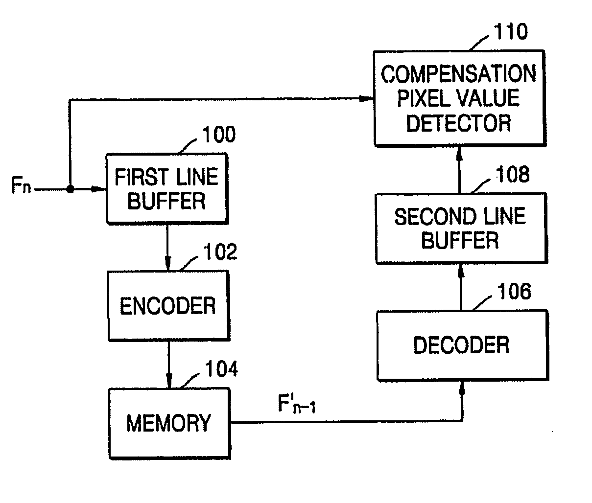
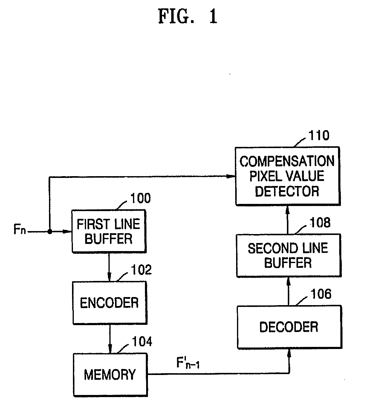
[0030]FIG. 1 is a block diagram of an apparatus for performing Dynamic Capacitance Compensation (DCC) of a LCD, according to an embodiment of the present invention. The DCC apparatus includes a first line buffer 100, an encoder 102, a memory 104, a decoder 106, a second line buffer 108, and a compensation pixel value detector 110.

[0031] The first line buffer 100 reads and temporarily stores pixel values of an image for each line. In detail, the first line buffer 100 reads pixel values of an image of a current frame Fn for eac...


PUM


Abstract

There are provided an apparatus and method for performing dynamic capacitance compensation (DCC) in a liquid crystal display (LCD). The DCC apparatus includes: a first line buffer reading and temporarily storing pixel values of an image for each line; an encoder transforming and quantizing the pixel values stored for each line for each block and generating bit streams; a memory storing the generated bit streams; a decoder decoding the bit streams stored in the memory for the each block and outputting the decoded bit streams; a second line buffer reading and temporarily storing the decoded pixel values for the each block; and a compensation pixel value detector detecting a compensation pixel value for each pixel, from pixel value differences between pixel values of a current frame stored in the first line buffer and pixel values of a previous frame stored in the second line buffer. Therefore, it is possible to reduce the number of pins of a memory interface by reducing the number of memory device for storing pixel values of image data, required for performing DCC of a LCD, resulting in minimizing a chip size, and to enhance compression efficiency without visual deterioration in images.

Description

CROSS-REFERENCE TO RELATED APPLICATION [0001] This application claims the benefit of Korean Patent Application No. 10-2004-0091850, filed on Nov. 11, 2004, in the Korean Intellectual Property Office, the disclosure of which is incorporated herein in its entirety by reference. BACKGROUND OF THE INVENTION [0002] 1. Field of the Invention [0003] The present invention relates to Dynamic Capacitance Compensation (DCC) for a Liquid Crystal Display (LCD), and more particularly, to an apparatus and method for performing Dynamic Capacitance Compensation (DCC) of a Liquid Crystal Display (LCD), capable of minimizing a chip size and reducing picture-quality deterioration. [0004] 2. Description of the Related Art [0005] A Liquid Crystal Display (LCD) displays characters or images using optical variations caused by injecting and arranging liquid crystals between two glass plates and then applying a voltage to change the arrangement of the liquid crystal particles. Since the LCD uses a low voltag...

Claims


Application Information

Patent Timeline
IPC IPC(8): G06K9/36
CPCG09G3/3611G09G5/39G09G2320/0252G09G2340/02G09G2340/16G09G3/36
Inventor KIM, WOOSHIKLEE, SEUNGWOOKIM, WOOCHULBIRINOV, DMITRY
Owner SAMSUNG ELECTRONICS CO LTD
Learn More