
Direct type backlight module

a backlight module and direct type technology, applied in lighting and heating apparatus, lighting device details, instruments, etc., can solve the problems of color deterioration, increase the difficulty of compacting the backlight module, etc., to improve the total brightness and uniformity, improve the insufficient brightness occurring

Inactive Publication Date: 2006-05-11
CORETRONIC
View PDF4 Cites 59 Cited by
  • Summary
  • Abstract
  • Description
  • Claims
  • Application Information

AI Technical Summary

Benefits of technology

[0009] One objective of the present invention is to provide a direct type backlight module for improving the insufficient brightness occurring between any two neighboring light-emitting elements and further to increase the total performance of the brightness and uniformity.
[0010] To achieve the objective mentioned above, in the present invention, light-compensating elements are installed at the regions between any two neighboring light-emitting elements to improve the brightness defects occurring in the regions between any two neighboring light-emitting elements so as to increase the brightness and uniformity of a planar backlight source.
[0011] Also to achieve the objectives mentioned above, the present invention utilizes a structure of total-reflection prisms to realize the aforementioned light-compensating element. In one preferred embodiment of the present invention, the light-compensating elements are disposed at the positions that are above the regions between any two neighboring CCFLs and intervene between the diffuser and the CCFLs. In another preferred embodiment of the present invention, the structures of total-reflection prisms are formed directly onto some regions of the bottom of the diffuser, wherein those regions correspond to the positions intervening between any two neighboring CCFLs. The light emitted from two lateral sides of the CCFL is guided to some regions of the diffuser, wherein those regions correspond to the positions intervening between any two neighboring CCFLs, in order to compensate the brightness in those regions and increase the total performance of the brightness and uniformity.

Problems solved by technology

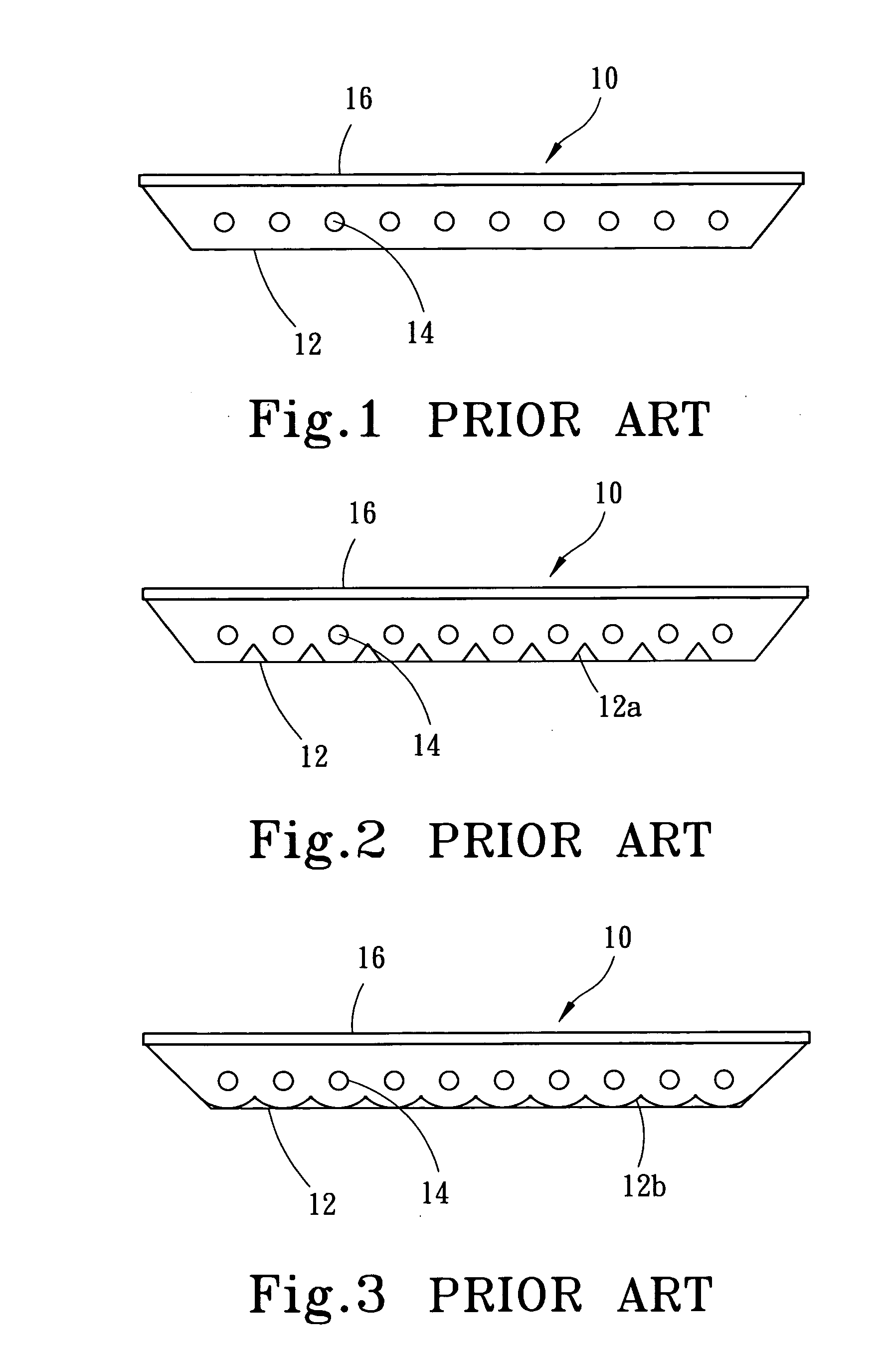
Although improving the brightness defects occurring in the regions between any two neighboring CCFLs 14, those methods will increase the difficulty of compacting the backlight module.
Further, the printed light-shielding pattern 19 also has a problem of the color deterioration resulting from an ink aging.

Method used


Image

  • Direct type backlight module
  • Direct type backlight module
  • Direct type backlight module

Examples


Embodiment Construction

[0025]FIG. 7 shows a structural diagram of the structure of a first preferred embodiment, wherein the direct type backlight module 100 that utilizes a CCFL 120 as a light source. The direct type backlight module 100 of the present invention comprises a reflector 110, a plurality of CCFLs, a diffuser 130 and a plurality of light-compensating elements 140.

[0026] A plurality of CCFLs 120 is disposed inside the reflector 110 and arranged in parallel with each other in an appropriate spacing. The diffuser 130 is placed over the reflector 110 and positioned above the CCFLs 120. The diffuser 130 is an optical plate, which provides the light with a fogging effect, has an incident face 131 fronting the CCFLs and an exit face 132 opposite to the incident face 131, and the light emitted from the exit face 132 of the diffuser 130 has a uniform brightness. The light-compensating elements 140 are disposed at regions corresponding to those positions between any two neighboring CCFLs 120 and inter...


PUM


Abstract

The present invention relates to a direct type backlight module providing a planar backlight source, wherein it adopts several light-emitting elements, and the light emitted from the light-emitting elements directly illuminates a diffuser, or is reflected by a reflector, and then the reflected light illuminates the diffuser. Via light-compensating elements installed between any two neighboring light-emitting elements, the present invention solves the brightness defects occurring in the portions between any two neighboring light-emitting elements and further increases the brightness and uniformity of a planar backlight source.

Description

FIELD OF THE INVENTION [0001] The present invention relates to a direct type backlight module, particularly to a direct type backlight module, which has a promoted brightness and uniformity via providing additional light-compensating elements to improve the brightness defects occurring in the regions between any two neighboring light-emitting elements. BACKGROUND OF THE INVENTION [0002] Generally speaking, a backlight module refers to an assembly of parts that provides a backlight source for the product. The typical application thereof is the backlight source of a flat panel display, such as a liquid crystal display LCD. The light-emitting elements currently used by a backlight module include: electron luminescence (EL), cold cathode fluorescent lamp (CCFL), and light-emitting diode (LED). According to the position for the backlight source, a backlight module can be divided into the direct type and the edge-side type. [0003] The light-emitting elements currently used by the direct t...

Claims


Application Information

Patent Timeline
Patent Type & Authority Applications(United States)
IPC IPC(8): F21V13/04
CPCG02F1/133604G02F1/133606G02F1/133611G02F2001/133507G02F2001/133607G02F1/133507G02F1/133607G02F1/1335
Inventor LIU, MING-DAHKUO, HAO-JAN
Owner CORETRONIC
Learn More