Photography device and photography processing method
a technology of a processing method and a camera, which is applied in the direction of color television details, television system details, television systems, etc., can solve the problems of image that is captured at a time of photography relative to a shutter operation, and the moment of shooting may be los
- Summary
- Abstract
- Description
- Claims
- Application Information
AI Technical Summary
Benefits of technology
Problems solved by technology
Method used
Image

Examples
first embodiment
[0023] First Embodiment
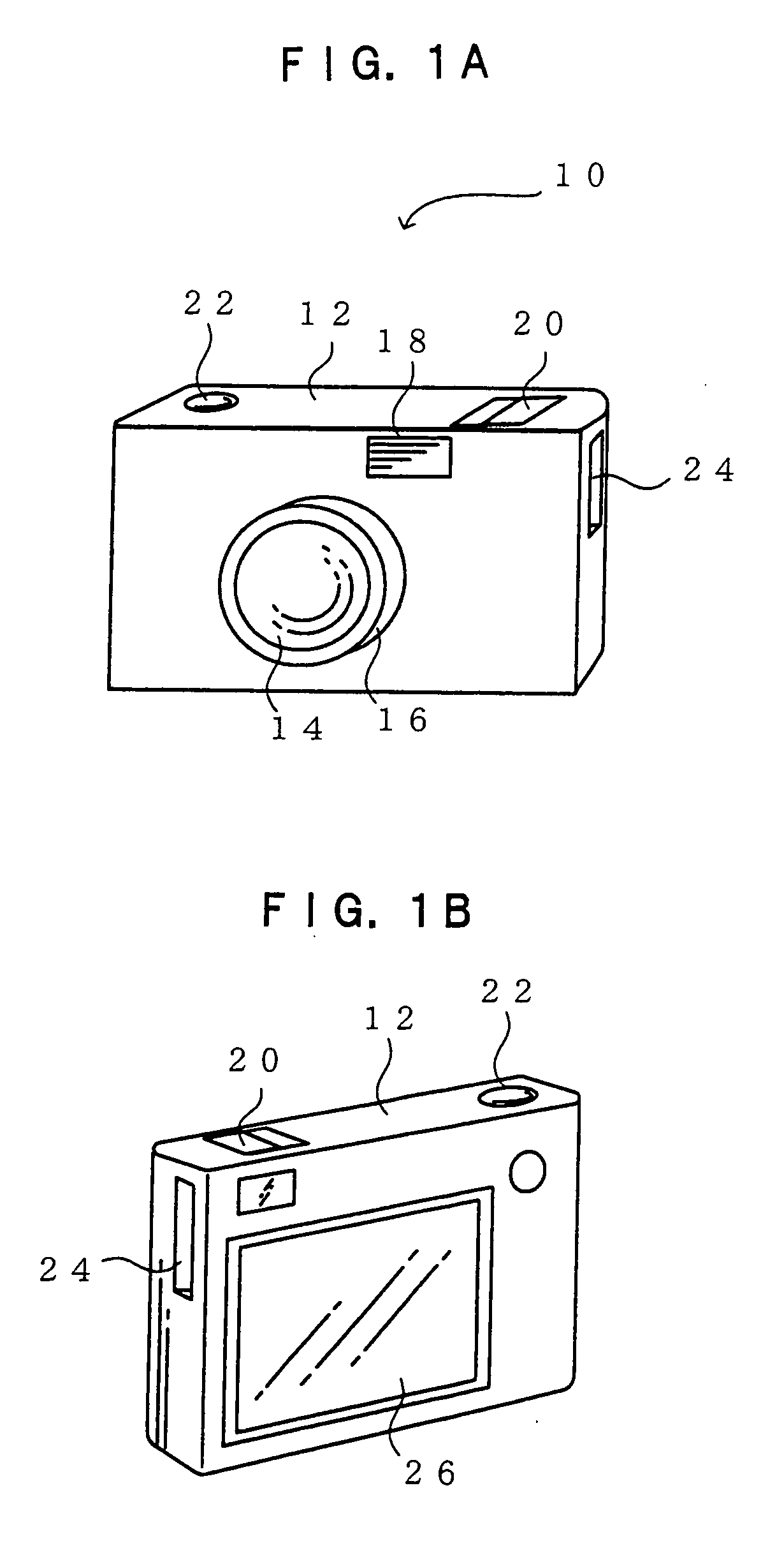
[0024]FIGS. 1A and 1B are perspective views showing the exterior of a digital camera relating to a first embodiment of the present invention.
[0025] As shown in FIGS. 1A and 1B, a main body 12 of a digital camera 10 is substantially box-shaped. A lens barrel 16, at which a lens 14 is mounted, is provided at the middle of a front face side of the main body 12.
[0026] A flash 18 is provided upward of the lens 14 of the main body 12. The flash 18 is for emitting light to assist in cases of photography in low illumination and the like.
[0027] A power switch 20 and a shutter button 22 are provided at an upper face of the main body 12, at a right side and a left side as viewed from the front face, respectively. A slot 24, at which a memory card (not shown) can be mounted, is provided at a right side face of the main body 12 as viewed from the front face.
[0028] The shutter button 22 is structured to be operable to two positions: a half-press and a full-press. AE (au...
second embodiment
[0057] Second Embodiment
[0058] Next, a digital camera relating to a second embodiment of the present invention will be described. Here, structures of the exterior and the electrical system of the digital camera are basically the same as in the first embodiment. Therefore, descriptions thereof are omitted. Furthermore, in the following descriptions, structures that are the same as in the first embodiment are assigned the same reference numerals for description.
[0059]FIG. 6 is a functional block diagram showing detailed structure for when an image is to be displayed at the display 26 of the digital camera relating to the second embodiment of the present invention.
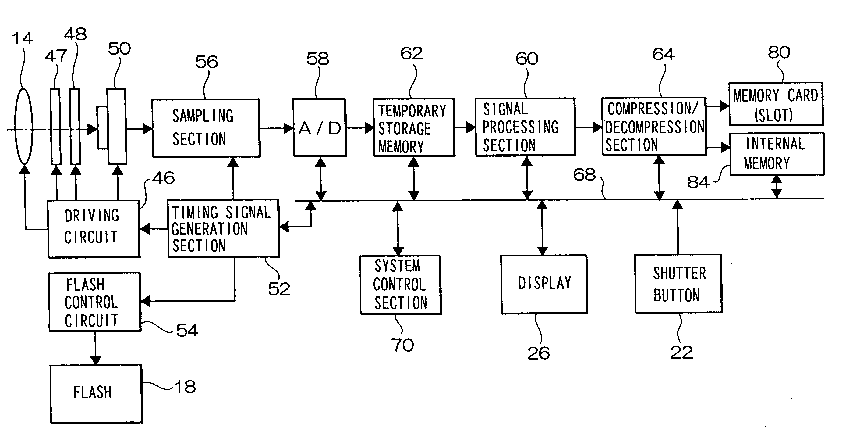
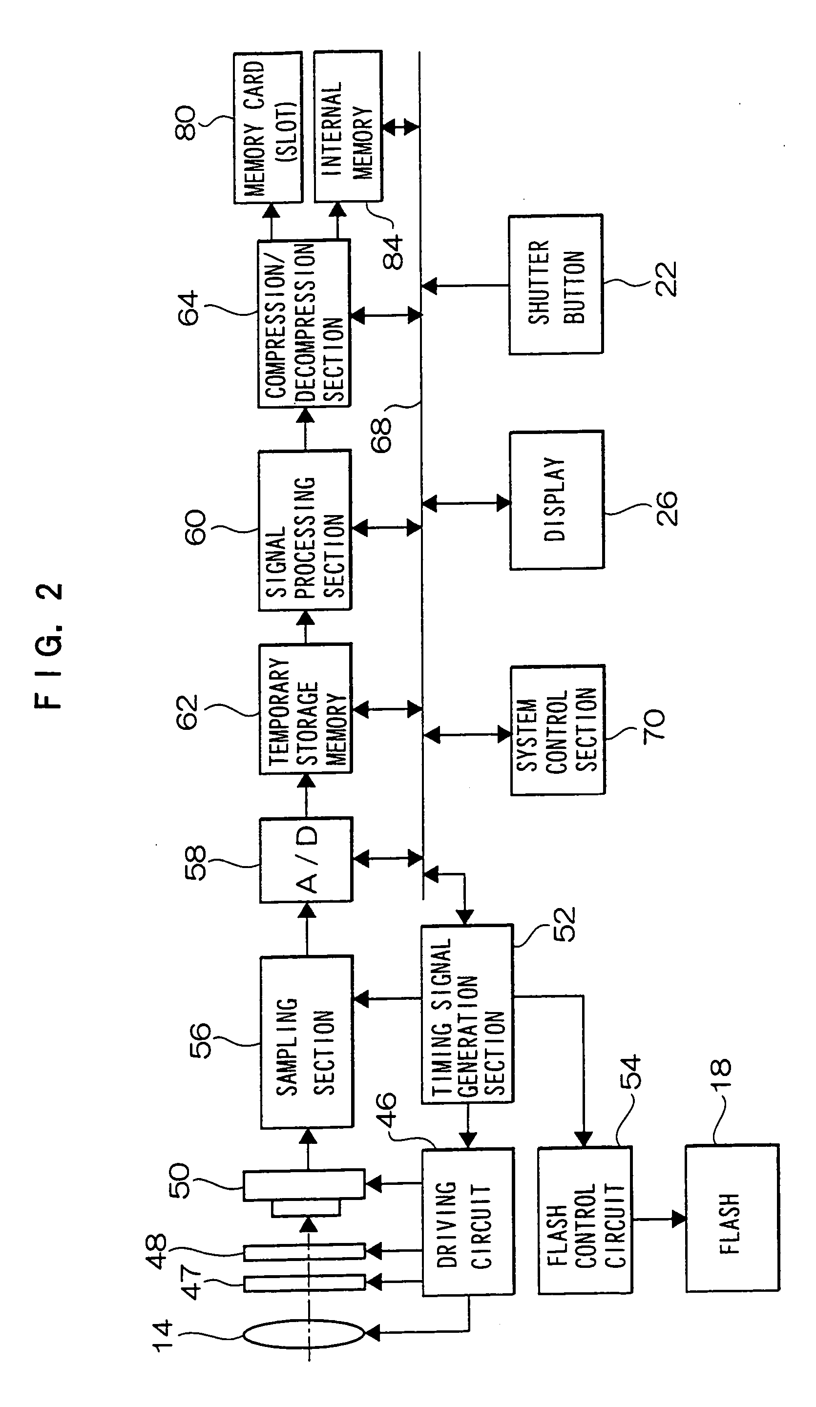
[0060] A subject image is imaged at the image capture device 50, via the lens 14, the AF lens 47 and the aperture 48, is outputted from the image capture device 50 as image data, and is inputted to the signal processing section 60 via the above-described sampling section 56 and A / D converter 58.
[0061] The image data inputt...
third embodiment
[0077] Third Embodiment
[0078] Next, a digital camera relating to a third embodiment will be described. Here, structures of the exterior and the electrical system of the digital camera are basically the same as in the first embodiment. Therefore, descriptions thereof are omitted. Furthermore, in the following descriptions, structures that are the same as in the first embodiment are assigned the same reference numerals for description.
[0079]FIG. 8 is a functional block diagram showing detailed structure for when an image is to be displayed at the display 26 of the digital camera relating to the third embodiment.
[0080] As shown in FIG. 8, similarly to the first and second embodiments, the system control section 70 of the digital camera relating to the third embodiment is structured to include the selection section 72 and the delay duration detection section 74. In addition, in the third embodiment, the system control section 70 is structured to also include a storage selection sectio...
PUM
 Abstract
Description
Claims
Application Information
 - R&D
- Intellectual Property
- Life Sciences
- Materials
- Tech Scout
- Unparalleled Data Quality
- Higher Quality Content
- 60% Fewer Hallucinations
Browse by: Latest US Patents, China's latest patents, Technical Efficacy Thesaurus, Application Domain, Technology Topic, Popular Technical Reports.
© 2025 PatSnap. All rights reserved.Legal|Privacy policy|Modern Slavery Act Transparency Statement|Sitemap|About US| Contact US: help@patsnap.com