
Vehicle rearview mirror assembly incorporating a communication system

a communication system and rearview mirror technology, applied in the field of rearview mirror assemblies, can solve the problems of increasing the complexity of the onstar® system wiring, the inability to install the microwave antenna to receive the microwave signals from the satellites, and the inability to meet the needs of the vehicle, so as to reduce the need for additional wiring, and be easy to install in the vehicle.

Inactive Publication Date: 2006-05-11
GENTEX CORP
View PDF99 Cites 91 Cited by
  • Summary
  • Abstract
  • Description
  • Claims
  • Application Information

AI Technical Summary

Benefits of technology

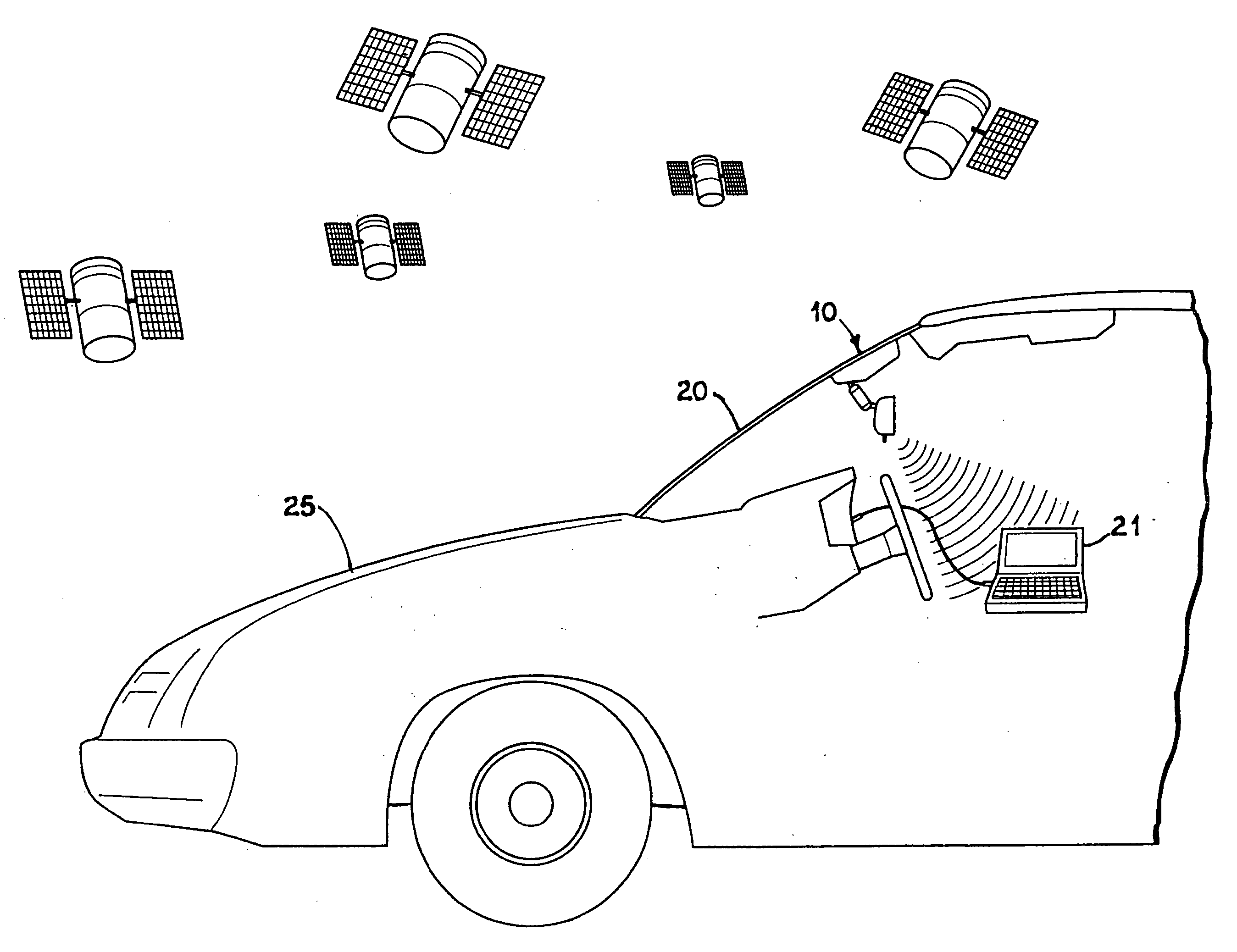
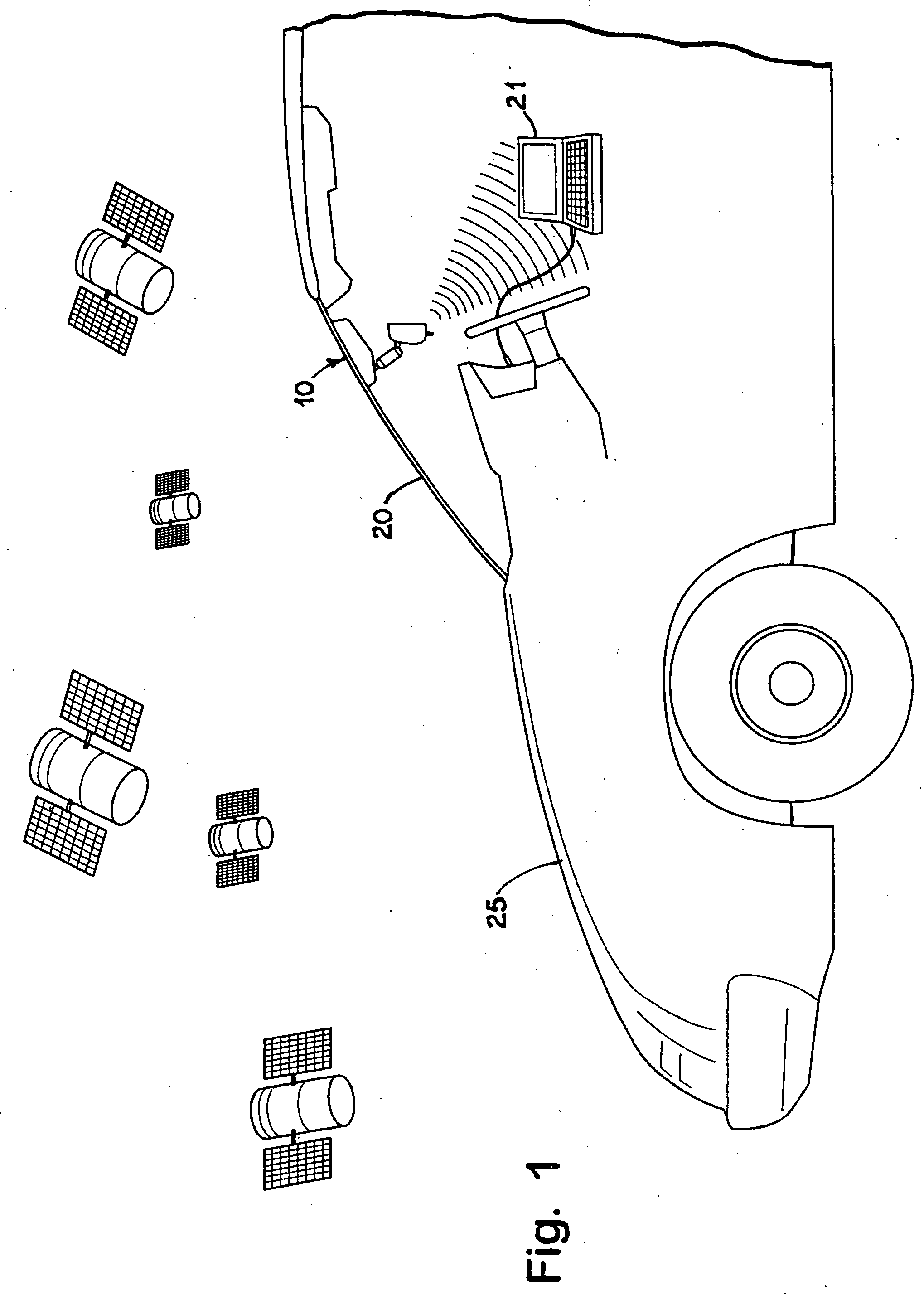
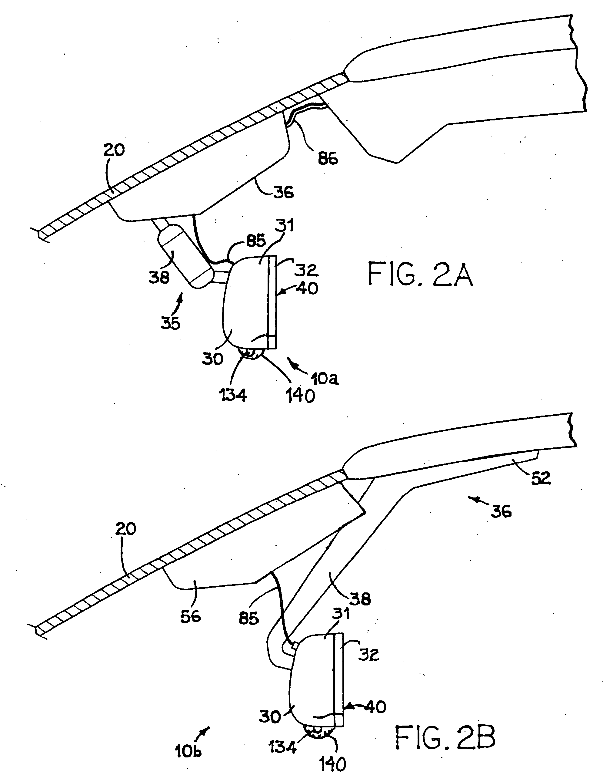
[0009] One aspect of the present invention is to provide a vehicle communication and control system that may be more readily installed in a vehicle and that utilizes minimal additional wiring. To achieve this and other aspects and advantages, the electrical components of the “brick” of a communication and control system are integrated into a rearview mirror assembly. Preferably, the microwave antenna for the GPS and the cellular telephone antenna are also integrated into the rearview mirror assembly. While it is preferable to integrate all the components of the system into the rearview mirror assembly in order to reduce the need to run additional wiring and to provide a system that is much easier to install, the present invention broadly is considered to be the combination of any two or more of the following components integrated within a rearview mirror assembly: a microwave antenna, a microwave receiver, a wireless communication device, such as a cellular telephone and its antenna, a Bluetooth™ transceiver, a Bluetooth™ controller, a Bluetooth™ antenna, at least one microphone, a digital signal processor, at least one speaker, a speech synthesizer, a voice recognition circuit including any voice recognition software, an electrochromic mirror, an electronic compass, map lamps, a moisture sensor, a headlamp sensor, a back-up power supply, a display, a vehicle bus interface, and an audio processing circuit. The present invention broadly pertains not only to various combinations of the above features, but also to the various disclosed, inherent, and implicit benefits and functions that flow from such features.

Problems solved by technology

All this wiring makes the system difficult and expensive to implement.
When offered as a dealer-installed option, the wiring complexity of the ONSTAR® system becomes even more of a problem.
Despite all the research that has been conducted and all the literature that has been generated relating to the use of position identification systems (GPS) in vehicular applications, little consideration had been given to the practicalities of where to mount the microwave antenna that is to receive the microwave signals from the satellites.
Installing the antenna in this position is difficult.
The separation of the receiver circuit from the antennas introduces significant manufacturing difficulties.
Coaxial cable typically used to connect the antenna to the receiver is expensive and difficult to handle in a manufacturing process, since it cannot be kinked and is relatively difficult to terminate.
Furthermore, such coaxial cable typically has relatively expensive push-on or screw-on type connectors that connect it to the system receiver circuit and / or microwave antenna.
Additionally, vehicle manufacturers have expressed an unwillingness to require their assembly line workers to connect the components using such a coaxial connector.
While WO 97 / 21127 further suggests that the antenna could additionally be positioned within an interior mirror of the vehicle, doing so is not preferred because the interior mirror is movable with respect to the passenger compartment, which may introduce error in the vehicle position measurements.
However, it does not work as well.
Having an antenna and its radiation pattern changing as different people get in the car and adjust the mirror is extremely undesirable.
Further, WO 97 / 21127 additionally states that metallic coatings on the vehicle windshield may interfere with the operation of a receiving antenna when mounted in an interior rearview mirror assembly.
Additionally, like the configuration where the receiving antennas are mounted in the two exterior mirrors, the mounting of the receiving antenna in the interior rearview mirror housing also presents manufacturing problems associated with connecting the antenna with the receiver, which apparently is mounted in the vehicle instrument panel.
As noted above, it is very difficult to install a vehicle communication and control system in a vehicle.
Furthermore, the next vehicle model this system is added to is likely to require a different installation.

Method used


Image

  • Vehicle rearview mirror assembly incorporating a communication system
  • Vehicle rearview mirror assembly incorporating a communication system
  • Vehicle rearview mirror assembly incorporating a communication system

Examples


Embodiment Construction

[0087] Reference will now be made in detail to the present preferred embodiments of the invention, examples of which are illustrated in the accompanying drawings. Wherever possible, the same reference numerals will be used throughout the drawings to refer to the same or like parts.

[0088] As noted above, the present invention pertains to a vehicle rearview assembly that incorporates some or all of the components of a vehicle communication and control system. As used herein, a “rearview assembly” is a structure that provides an image of a scene to the rear of driver. As commonly implemented, such rearview assemblies include an appropriately positioned mirror. A rearview assembly may additionally or alternatively include an electronic display that displays an image as sensed by a camera or other image sensor (see, for example, U.S. patent application Ser. No. 09 / 153,654 entitled SYSTEMS AND COMPONENTS FOR ENHANCING REAR VISION FROM A VEHICLE, filed on Sep. 15, 1998, by Frederick T. Ba...


PUM


Abstract

A vehicle communication and control system is provided that may be more readily installed in a vehicle and that utilizes minimal additional wiring. According to some of the disclosed embodiments, the electrical components of the “brick” of a communication and control system are integrated into a rearview mirror assembly. Preferably, the microwave antenna for the GPS and the cellular telephone antenna are also integrated into the rearview mirror assembly. Various functions and features of the system are also disclosed.

Description

CROSS-REFERENCE TO RELATED APPLICATIONS [0001] This application is a divisional of U.S. patent application Ser. No. 09 / 827,304 entitled VEHICLE REARVIEW MIRROR ASSEMBLY INCORPORATING A COMMUNICATION SYSTEM, filed on Apr. 5, 2001, by Robert R. Turnbull et al., and claims priority under 35 U.S.C. §119(e) on U.S. Provisional Application No. 60 / 242,465 entitled VEHICLE REARVIEW MIRROR ASSEMBLY INCORPORATING A COMMUNICATION SYSTEM, filed on Oct. 23, 2000, by Robert R. Turnbull et al.; U.S. Provisional Application No. 60 / 216,297 entitled VEHICLE REARVIEW MIRROR ASSEMBLY INCORPORATING A COMMUNICATION SYSTEM, filed on Jul. 6, 2000, by Robert R. Turnbull et al.; and to U.S. Provisional Application No. 60 / 195,509 entitled VEHICLE REARVIEW MIRROR ASSEMBLY INCORPORATING A COMMUNICATION SYSTEM, filed on Apr. 6, 2000, by Robert R. Turnbull et al., the entire disclosures of which are incorporated herein by reference.BACKGROUND OF THE INVENTION [0002] The present invention generally relates to a re...

Claims


Application Information

Patent Timeline
Patent Type & Authority Applications(United States)
IPC IPC(8): B60Q1/00B60R1/12H01Q1/32H01Q5/00H01Q5/371H01Q9/04H01Q9/30H01Q21/28H01Q21/30H04B1/38H04B1/3805H04B1/3822H04M1/02H04M1/21H04M1/27H04M1/60H04R1/08
CPCB60R1/12H01Q5/371B60R2001/1223B60R2001/1261B60R2001/1284B60W2050/0081H01Q1/3266H01Q9/0407H01Q9/30H01Q21/28H01Q21/30H04B1/3805H04B1/3822H04M1/271H04M1/6075H04M1/6091H04M2250/02H04M2250/10H04R1/08H04R2499/13B60R1/1207B60W2050/0075B60W2556/60
Inventor TURNBULL, ROBERT R.KNAPP, ROBERT C.WALSTRA, ERIC J.WATSON, ALAN R.POE, G. BRUCEROBERTS, JOHN K.RUMSEY, WAYNE J.
Owner GENTEX CORP
Learn More