
Exercise machine and method for use in training selected muscle groups

a technology of exercise machine and muscle group, applied in the field of exercise machines, can solve the problems of inability to train the muscles that need to be trained, flywheel inertia, and inability to provide training

Inactive Publication Date: 2006-05-04
DAY FRLIN J
View PDF73 Cites 86 Cited by
  • Summary
  • Abstract
  • Description
  • Claims
  • Application Information

AI Technical Summary

Benefits of technology

[0014] In particular, the present invention provides an exercise machine which controllably provides resistance to movement of a crank, and that controllably varies resistance to crank movement in response to one or more of several considerations that may include crank position, direction of crank motion, crank speed, and crank acceleration, in order to provide an amount of resistance to the motion of one or each of the cranks where and when such resistance will be most useful in providing exercise to improve the user's fitness. In an exercise machine which is one preferred embodiment, resistance is varied during each crank rotation so as to provide the most desirable resistance in an angular sector of each rotation where it will be most useful to train selected specific muscle groups of the user, or in simulating the varying requirements for efforts during an actual bicycle ride.
[0019] In one preferred embodiment of the invention, such a control system is arranged to provide resistance to rotation of a pair of cranks in a way that simulates the resistance to pedal movement experienced by a bicyclist during a bicycle ride on terrain of varying slopes and allows the user to regulate the amount of resistance by providing a signal that causes the control system to simulate the result of shifting the gears of a bicycle to respond to the slopes of the terrain or desired speed or effort on that terrain. For example, downhill slopes can be simulated by applying no resistance to crank rotation as long as crank speed is less than would be necessary to further accelerate the bicycle moving at the simulated speed using a simulated gearing selection. In this way “coasting” under any condition can be appropriately simulated.

Problems solved by technology

While such exercise machines are useful in improving the fitness of a healthy user, they are not particularly useful in providing training for rehabilitation of specific muscle groups in injured users or athletes trying to improve function of specific muscles or to improve a particular coordination pattern.
A pair of opposed cranks continuously connected to a flywheel, however, may result in flywheel inertia, or torque applied to one crank, being used to make up for weakness of injured muscles working on the opposite crank.
As a result, muscles that need to be trained are not forced by the machine to work as much as might be desirable.
While it would be possible to put such a system on a bicycle it would require substantial modification of a typical bicycle.
Neither Day nor Moser, et. al. provides significant resistance when pedaling backwards.
Such previously available stationary exercise machines, however, fail to realistically simulate many of the variable requirements for effort experienced while actually riding a bicycle, such as needing to overcome the mass inertia of the rider when accelerating or decelerating and the tendency of the bicycle to accelerate when going downhill, even when not pedaling, and improvements are desired.
While some variable resistances are present in currently available exercise machines, many do not simulate the inertia of the bike / rider system which would require the user to put in enough excess energy in order to accelerate.
Another simulation defect of current machines is the inability to simulate the speeding up that occurs when coasting down hill without attempting to accelerate.

Method used


Image

  • Exercise machine and method for use in training selected muscle groups
  • Exercise machine and method for use in training selected muscle groups
  • Exercise machine and method for use in training selected muscle groups

Examples


Embodiment Construction

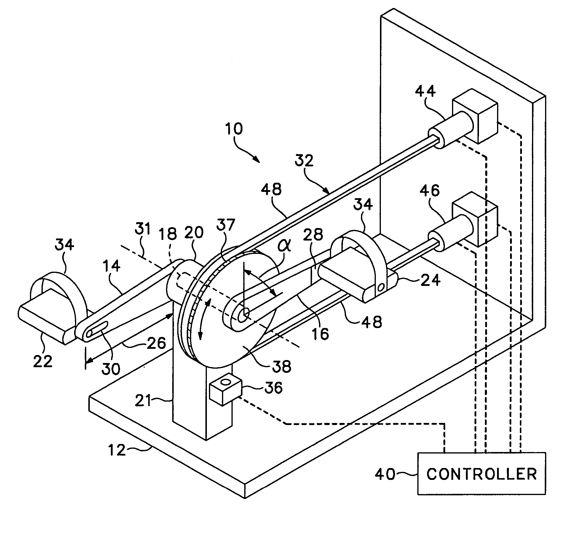
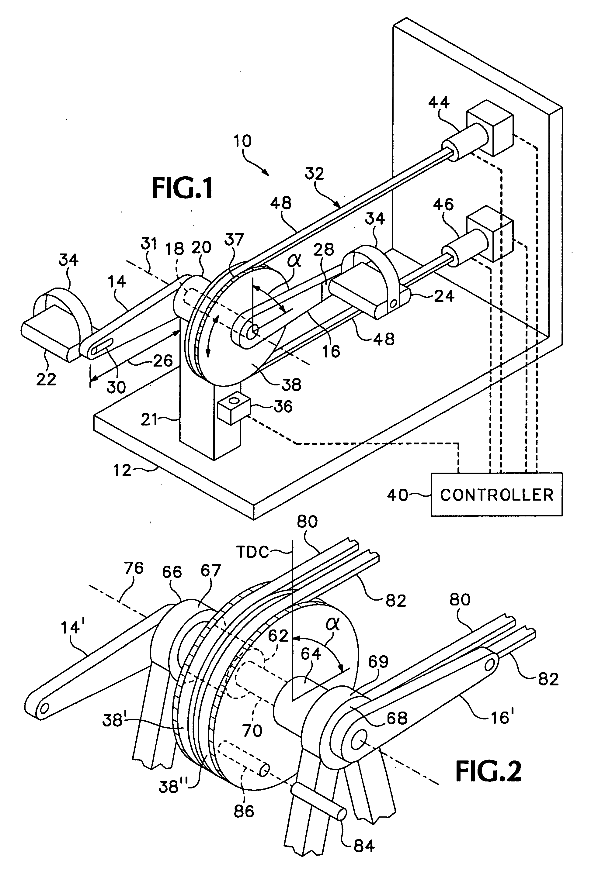
[0030] Referring to the drawings that form a part of the disclosure herein, an exercise apparatus 10 shown in FIG. 1 has a frame 12 on which a pair of cranks 14, 16 are mounted on a crankshaft 18 carried in suitable bearings 20 mounted at the top of the upright support member 21. The cranks 14, 16 carry pedals 22, 24 that may be attached at an adjustable distance 26 from the crankshaft 18, as by being mounted rotatably on a respective mounting plate 28 fastened to the crank 14 or 16 by a suitable fastener extending through a slot 30 defined in the crank.

[0031] Each crank 14, 16 is connected drivingly to the crankshaft 18, so that either of the cranks 14, 16 can independently cause the crankshaft 18 to rotate about an axis 31. An adjustable braking mechanism 32 is mounted on the frame 12 and can be operated quickly and precisely to provide increased or decreased resistance to rotation of the shaft. The braking mechanism can be of any of several types so long as the braking force can...


PUM


Abstract

An exercise machine and a method for its use in training selected muscle groups by controlled use of brakes to resist crank movement adjustably at specific and adjustable controlled positions in the rotation of a crank. A control system may be incorporated to cause brake mechanisms to apply varying amounts of resistance to a pair of pedal-driven cranks to simulate the efforts required to ride an actual bicycle over a course including various upslopes and down-slopes.

Description

BACKGROUND OF THE INVENTION [0001] The present invention relates to exercise machines, and in particular relates to an exercise machine incorporating one or more cranks and a method for use of such a machine in training selected muscle groups for athletic or therapeutic purposes. [0002] Exercise machines are well known in which handles or pedals are used to drive cranks connected to flywheels or fans that provide resistance to rotation of the cranks. Various brakes or other mechanisms are used in other exercise machines to provide desired amounts of resistance to rotation of the cranks, varying the resistance in response to operator control, as taught by Owens U.S. Pat. No. 4,934,692, or in response to the length of time during which the exercise machine is operated, or in response to the number of rotations of the crank, as in Johannson U.S. Pat. No. 3,501,142. While such exercise machines are useful in improving the fitness of a healthy user, they are not particularly useful in pr...

Claims


Application Information

Patent Timeline
Patent Type & Authority Applications(United States)
IPC IPC(8): A63B15/02A63B22/06A63B71/00
CPCA63B21/015A63B22/0007A63B22/0012A63B22/0605A63B24/00A63B2022/0005A63B2022/0623A63B2024/0078A63B2220/16A63B2220/24A63B2220/54A63B21/1496A63B21/4049A63B22/0005
Inventor DAY, FRANKLIN J.
Owner DAY FRLIN J
Learn More