
Moveable transparent barrier for x-ray analysis of a pressurized sample

a transparent barrier and sample technology, applied in the direction of material analysis using wave/particle radiation, x/gamma/cosmic radiation measurement, instruments, etc., can solve the problems of unreliable on-line measurement of sulfur level, inability to control fuel production and distribution, undesired sulfur residue, etc., to reduce background scattering, increase and decrease the pressure on the film, the effect of reducing friction

Active Publication Date: 2006-05-04
X-RAY OPTICAL SYSTEM INC
View PDF9 Cites 21 Cited by
  • Summary
  • Abstract
  • Description
  • Claims
  • Application Information

AI Technical Summary

Benefits of technology

"The present invention provides a technique for analyzing samples using x-ray, neutron ray, gamma ray or particle-beam radiation. A barrier, transparent to the radiation, is used to separate the sample from the analysis engine. The sample can be a liquid flowing through a pressurized pipeline, and the analysis engine can perform compositional analysis while the liquid is flowing. The technique allows for consistent pressure on the barrier and reduces background scatter. The invention also includes a system for moving the barrier and a sample chamber assembly for increasing and decreasing pressure on the barrier."

Problems solved by technology

However, controlling fuel production and distribution are problematic, as there are no robust methods for on-line measurement of sulfur level in fuels during their processing and distribution.
On-line analysis of fuels in a refinery and in pipelines, however, requires consideration of numerous operational issues not generally present in an off-line, laboratory setting.
The present inventors have discovered that x-ray stimulation creates sulfur ionization and adsorption at this interface over time and on certain types of barrier materials—leading to undesired sulfur residue and degradation of the barrier's x-ray transparency.

Method used


Image

  • Moveable transparent barrier for x-ray analysis of a pressurized sample
  • Moveable transparent barrier for x-ray analysis of a pressurized sample
  • Moveable transparent barrier for x-ray analysis of a pressurized sample

Examples


Embodiment Construction

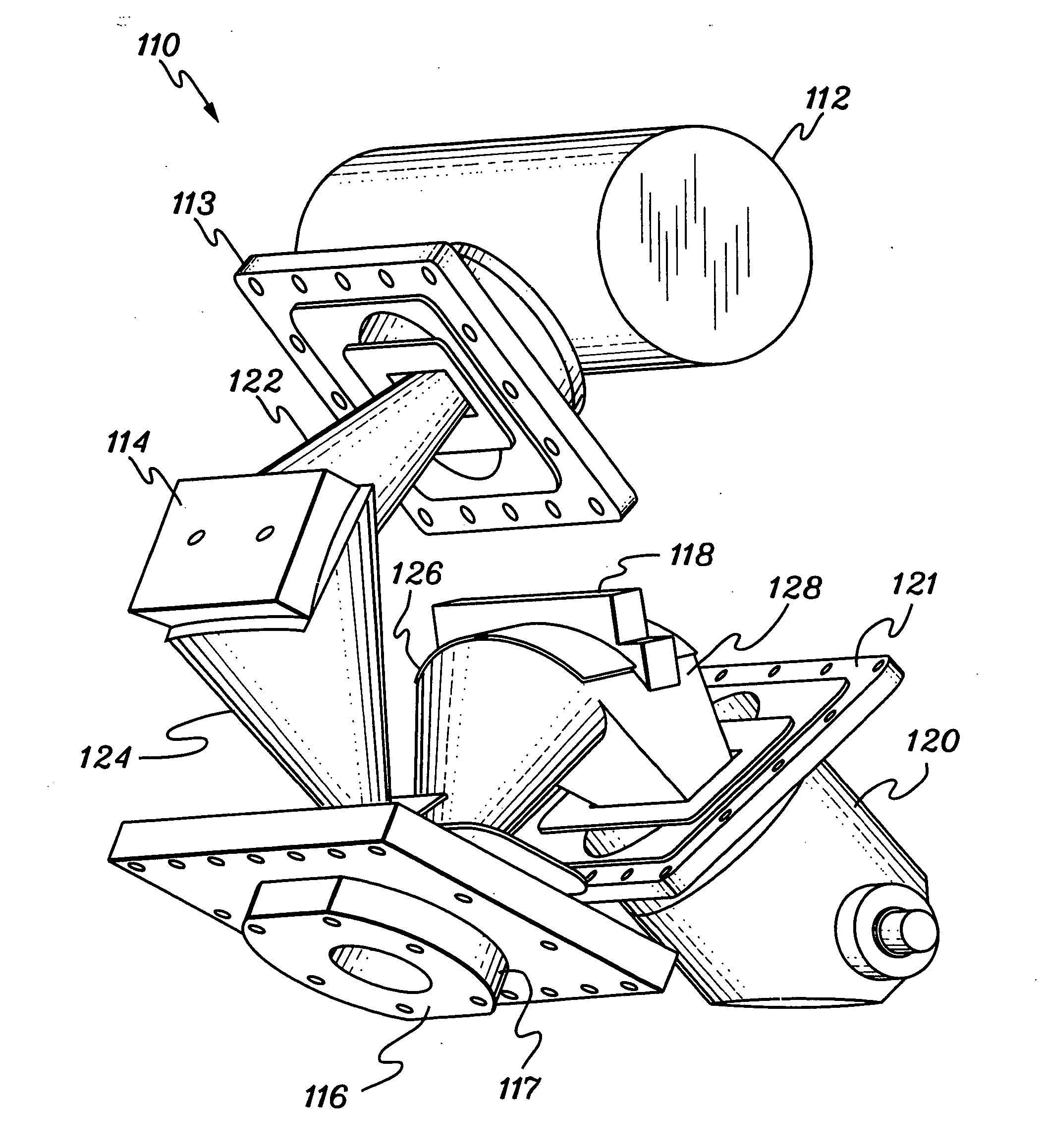
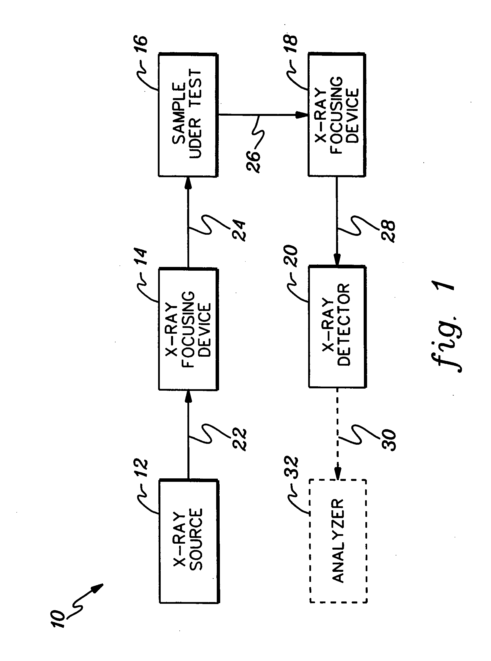
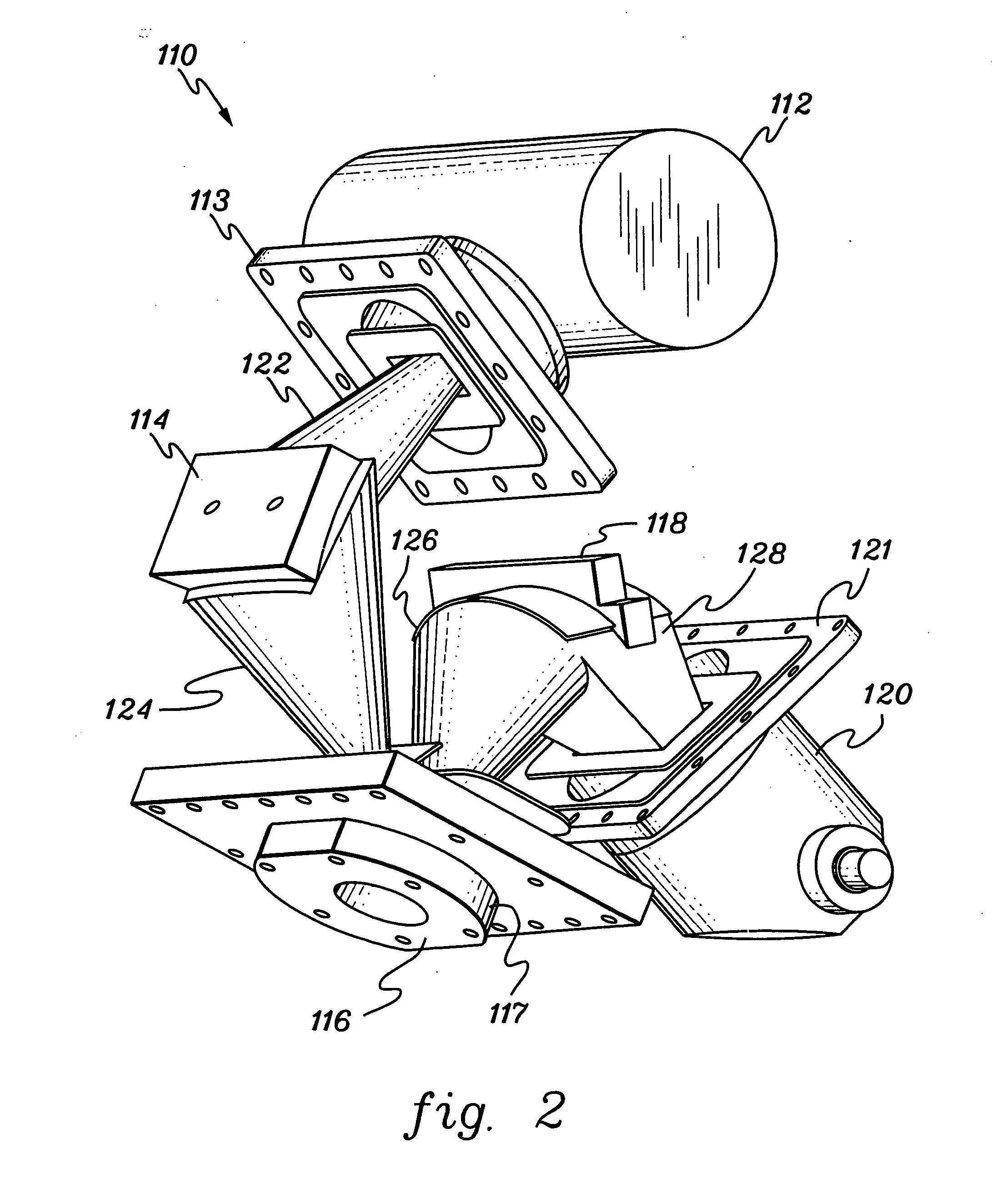
[0035]FIG. 1 is a schematic block diagram of a typical system 10 used for exposing a substance to x-ray radiation to produce fluorescent radiation which can then be detected and analyzed to determine a characteristic of the substance. The system typically includes an x-ray source 12, a first x-ray focusing device 14, a sample excitation chamber 16, a second x-ray focusing device 18, and an x-ray detector 20. The x-ray source 12, for example, an x-ray tube, produces a beam of x-rays 22. Though x-rays are used throughout the specification, the invention extends to neutron, particle-beam or gamma ray radiation Since x-ray beam 22 is typically a divergent beam, beam 22 is diffracted or focused by means of one or more x-ray focusing devices 14. X-ray focusing device 14 may be one or more doubly-curved crystals, for example, a doubly-curved crystal having essentially parallel atomic planes, such as the crystals disclosed in pending application Ser. No. 09 / 667,966 filed on Sep. 22, 2000 (A...


PUM

PropertyMeasurementUnit
pressuresaaaaaaaaaa
diameteraaaaaaaaaa
transparentaaaaaaaaaa

Abstract

A technique is disclosed for presenting a sample to a radiation interface of an analysis engine employing x-ray, neutron ray, gamma ray or particle-beam radiation to analyze the sample. A protective barrier, transparent to the radiation, and separating the sample from the engine, is moveable relative to the radiation interface, using a barrier movement system. The barrier in one embodiment is a film movable over a cavity in which the sample placed, and moveable with a system of reels to provide and retrieve a generally continuous supply of film over the cavity. The cavity may form a portion of a sample path through which the sample is moveable. If the sample path is pressurized, the film maintains the pressure during analysis of the sample by the analysis engine.

Description

CROSS-REFERENCE TO RELATED APPLICATIONS [0001] This application is a continuation of PCT Application PCT / US2004 / 019256 filed Jun. 16, 2004, and published under the PCT Articles in English as WO 2004 / 113894 A1 on Dec. 29, 2004. PCT / US2004 / 019256 claimed priority to U.S. Provisional Application No. 60 / 479,035, filed Jun. 17, 2003. The entire disclosures of PCT / US2004 / 019256 and U.S. Ser. No. 60 / 479,035 are incorporated herein by reference in their entirety. In addition, this application contains subject matter which is related to the subject matter of the following applications, which are hereby incorporated herein by reference in their entirety: [0002]“XRF SYSTEM INCLUDING FOCUSING OPTIC ON EXCITATION SIDE AND MONOCHROMATIC COLLECTION” by Chen, et al. U.S. Ser. No. 60 / 299,371 filed Jun. 19, 2001 (attorney docket 0444.042); [0003]“X-RAY TUBE AND METHOD AND APPARATUS FOR ANALYZING FLUID STREAMS USING X-RAYS” by Radley, et al. U.S. Ser. No. 60 / 336,584 filed Dec. 4, 2001 (attorney docket...

Claims


Application Information

Patent Timeline
Patent Type & Authority Applications(United States)
IPC IPC(8): G01N23/223G01T1/36G01N33/28
CPCG01N23/223G01N2223/076G01N33/2835
Inventor GALLAGHER, BRIAN
Owner X-RAY OPTICAL SYSTEM INC
Learn More