
Human machine interface for vehicle

Inactive Publication Date: 2006-05-04
VISTEON GLOBAL TECH INC
View PDF27 Cites 78 Cited by
  • Summary
  • Abstract
  • Description
  • Claims
  • Application Information

AI Technical Summary

Benefits of technology

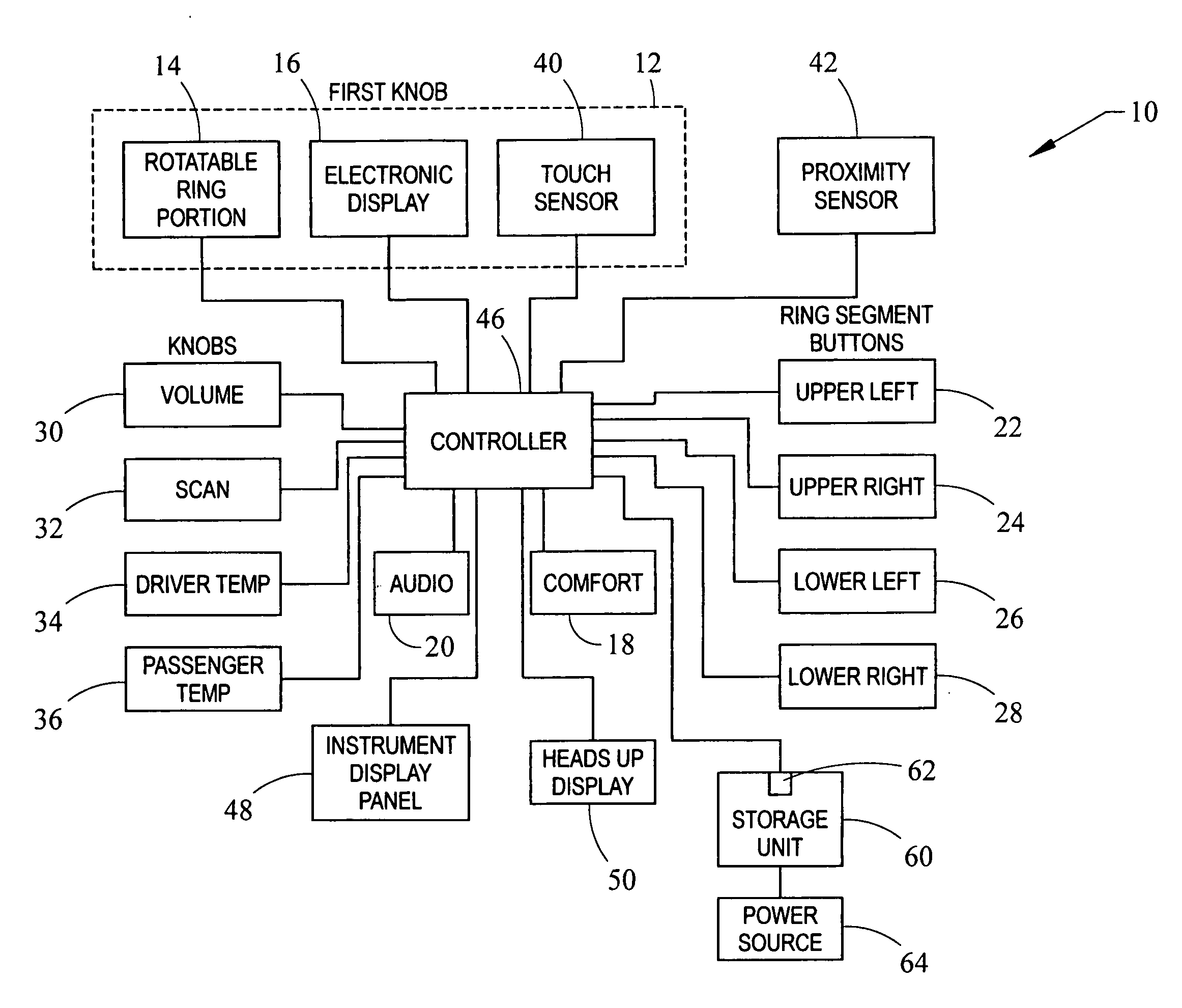
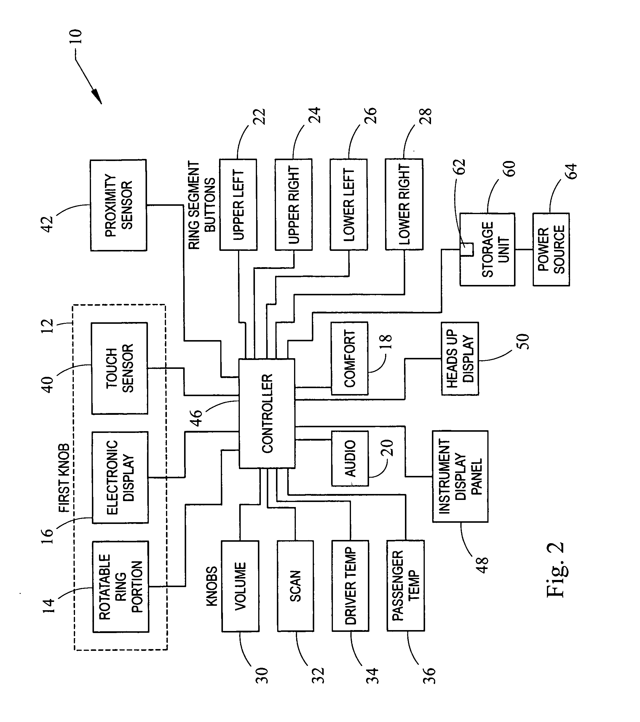
[0010] A proximity sensor is provided to sense user motion proximate the HMI unit. The proximity sensor signals a controller to copy content from the integrated display to a multifunction display in the instrument cluster or a heads up display to enable blind operation. In addition, a touch sensor is integrated on the ring knob to enlarge the adjustment display upon user contact. To avoid confusion of the driver, an enlarged display of the control function currently being manipulated is provided to the user. In addition, the enlarged display may include a symbol corresponding to the control function being manipulated. A portion of the background or other part of the display may be “filled-in”, where the fill area corresponds to the setting or level of the current control function. The background filling provides maximum visualization to the user and is easily rationalized by analogy, such as, the filling of a glass with water.
[0011] Menu buttons are provided for each function category. Preferably, each category function has no more than two menus per menu button. Two menus per button, allows the user to return to the desired main menu with one activation of any menu button. This enables an easily learnable HMI and reduces driver distraction while manipulating menus.
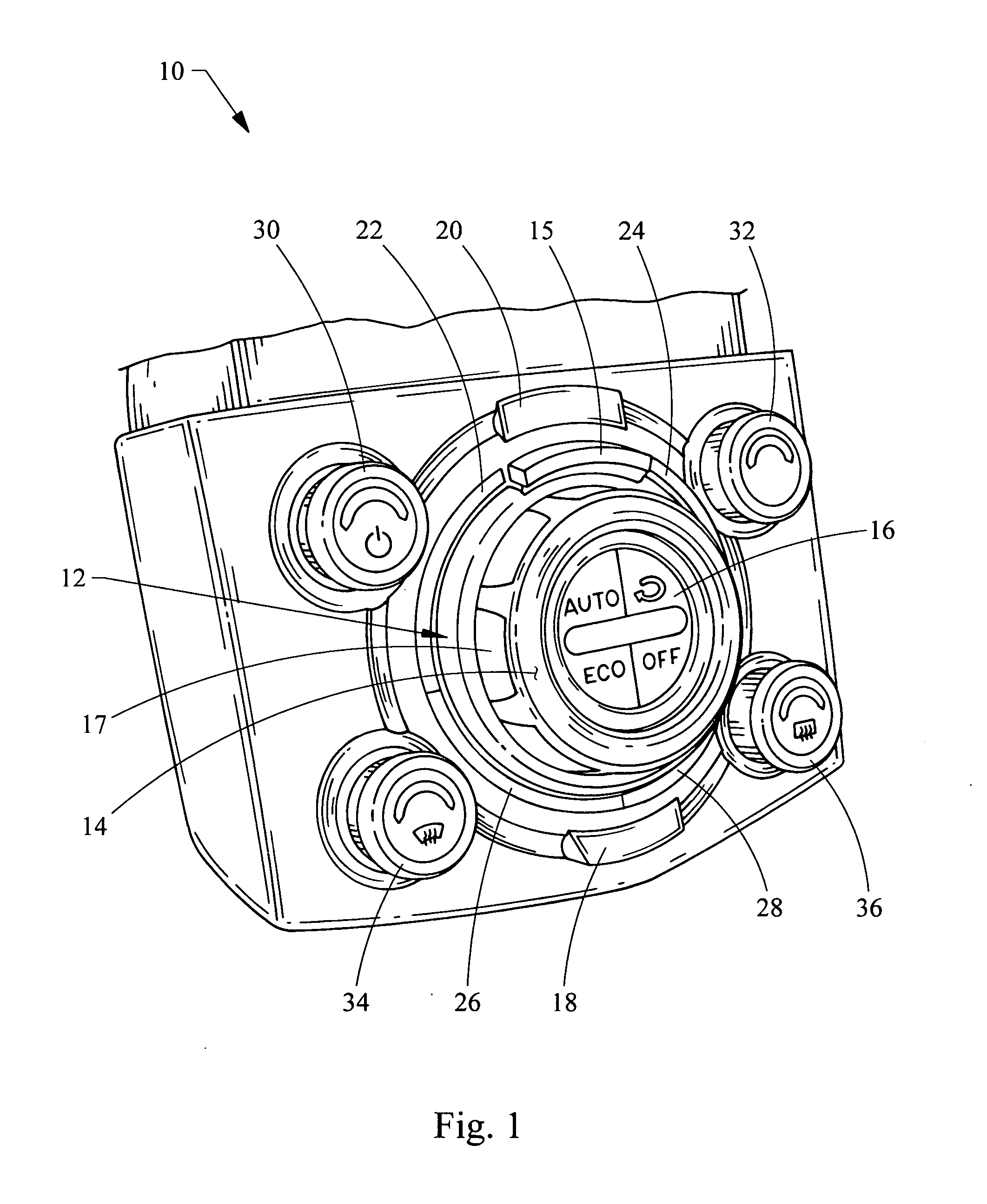
[0012] An arrangement of four ring segment buttons is provided around the display and ring knob. The operation of each button is supported by a visual feedback including the activation feedback and status feedback within the associated quarter segments of the round display integrated into the ring knob. Using a round display allows more styling flexibility and the division of the circle into four quarters provides a clean way for associating the four control functions to the four buttons that can be operated simultaneously. To provide further styling, the layout of the four ring segment buttons appear as a single ring or circle in the HMI unit.

Problems solved by technology

Today the number of controls for many interface units is limited by the cost of creating individual buttons and controls for each function.
Additionally, as the number of controls increase, the space required for the additional controls translates into higher cost and creates implementation problems for the design engineers.
Often budget and space constraints drive a reduction in interface optimization, even for high end customers.

Method used


Image

  • Human machine interface for vehicle
  • Human machine interface for vehicle
  • Human machine interface for vehicle

Examples


Embodiment Construction

[0030] Referring now to FIGS. 1 and 2, a human machine interface (HMI) unit embodying the principles of the present invention is illustrated therein and designated at 10. The HMI unit 10 includes various controls, an integrated display and a controller in communication with both the controls and display.

[0031] One control comprises a first knob 12 located central to the HMI unit 10 and includes an integrated electronic display 16. The first knob 12 includes a rotatable ring portion 14 located about the electronic display 16. The rotatable ring portion 14 has finger grips 17, preferably a tacky material for improved manipulation of the first knob 12. Positioned immediately above the first knob 12 and partially extends around the first knob 12 is a protrusion 15. As such, the protrusion 15 is available to the user as a finger rest allowing hand stabilization as the user manipulates the first knob 12, as illustrated in FIG. 3.

[0032] The first knob 12 also includes a touch sensor 40, ...


PUM


Abstract

A human machine interface includes a knob with an integrated electronic display located in the center of the knob. The knob may be used for operation with multiple functions corresponding to a menu on the electronic display. A plurality of buttons are located about the knob in the form of a circle and correspond to menu selections provided on the display.

Description

CROSS REFERENCE TO RELATED APPLICATIONS [0001] This application claims the benefit of U.S. provisional patent application No. 60 / 620,600, filed Oct. 20, 2004, which is incorporated herein by reference.BACKGROUND [0002] 1. Field of the Invention [0003] The present invention generally relates to a human machine interface (“HMI”) for a vehicle and more particularly for an HMI for a vehicle. [0004] 2. Description of Related Art [0005] Generally, interface designs try to maintain a one-to-one relationship between the controls and functions of the interface. Maximizing the one-to-one relationship of the functions to the controls of an interface provides intuitive navigation and improves ease of use of the system. In practice, many interfaces have buttons that control multiple functions of the interface by graphically associating the buttons with menu choices on a common display. [0006] Today the number of controls for many interface units is limited by the cost of creating individual butt...

Claims


Application Information

Patent Timeline
IPC IPC(8): G09G5/00G05G1/10G06F3/033G06F3/0482
CPCG05G1/105G06F3/0362G06F3/0482G06F3/04847B60H1/00985H01H9/181H01H19/025H01H25/065B60K35/00B60K35/10
Inventor CHOQUET, ALAINWEISS, MICHAELHARRIS, SIMON
Owner VISTEON GLOBAL TECH INC
Learn More