
Apparatus and method for forming inflated containers

a container and apparatus technology, applied in the field of apparatus and methods for forming containers, can solve the problems of not being able to produce adjacent cushions, producing cushions at a rate which is slower than would be desired, and large size of conventional machines for forming cushions, etc., and achieves the effect of no sacrifice in production speed

Active Publication Date: 2006-05-04
SEALED AIR U S
View PDF97 Cites 144 Cited by
  • Summary
  • Abstract
  • Description
  • Claims
  • Application Information

AI Technical Summary

Benefits of technology

[0010] Significantly, the first sealing device moves with the film web and produces the seals as the web is conveyed along the travel path. In this manner, container-size can be varied as desired without having to change film rolls, with no sacrifice in production speed. Moreover, the movable sealing device allows inflated containers of varying dimension to be produced, so that two or more adjacent containers in the film web can have different dimensions. Compound cushions comprising two or more inflated containers of two or more different sizes can thereby be produced.
[0013] b. a pressure mechanism that forms a pressure zone in the travel path in which the juxtaposed film plies are compressed. The pressure zone is positioned between the containers and the sealing zone to substantially isolate the containers from the sealing zone. Such isolation has been found to result in superior longitudinal seals.

Problems solved by technology

Conventional machines for forming inflated cushions tend to be rather large, expensive and complex, and produce cushions at a rate which is slower than would be desired.
While smaller, less-expensive inflation machines have been developed more recently, such machines generally make only one cushion-size at a time, i.e., they are not capable of producing adjacent cushions having different dimensions from the same web of film, because such machines generally operate with film webs having pre-formed containers.
The disadvantage of this approach is that the pre-formed containers have a predetermined size.
Thus, if different-sized cushions are desired, a different inflatable web must be installed on the machine, which results in the interruption of the cushion-making operation.
Even then, it is still not possible to produce adjacent cushions of different sizes on a real-time basis.

Method used


Image

  • Apparatus and method for forming inflated containers
  • Apparatus and method for forming inflated containers
  • Apparatus and method for forming inflated containers

Examples


Embodiment Construction

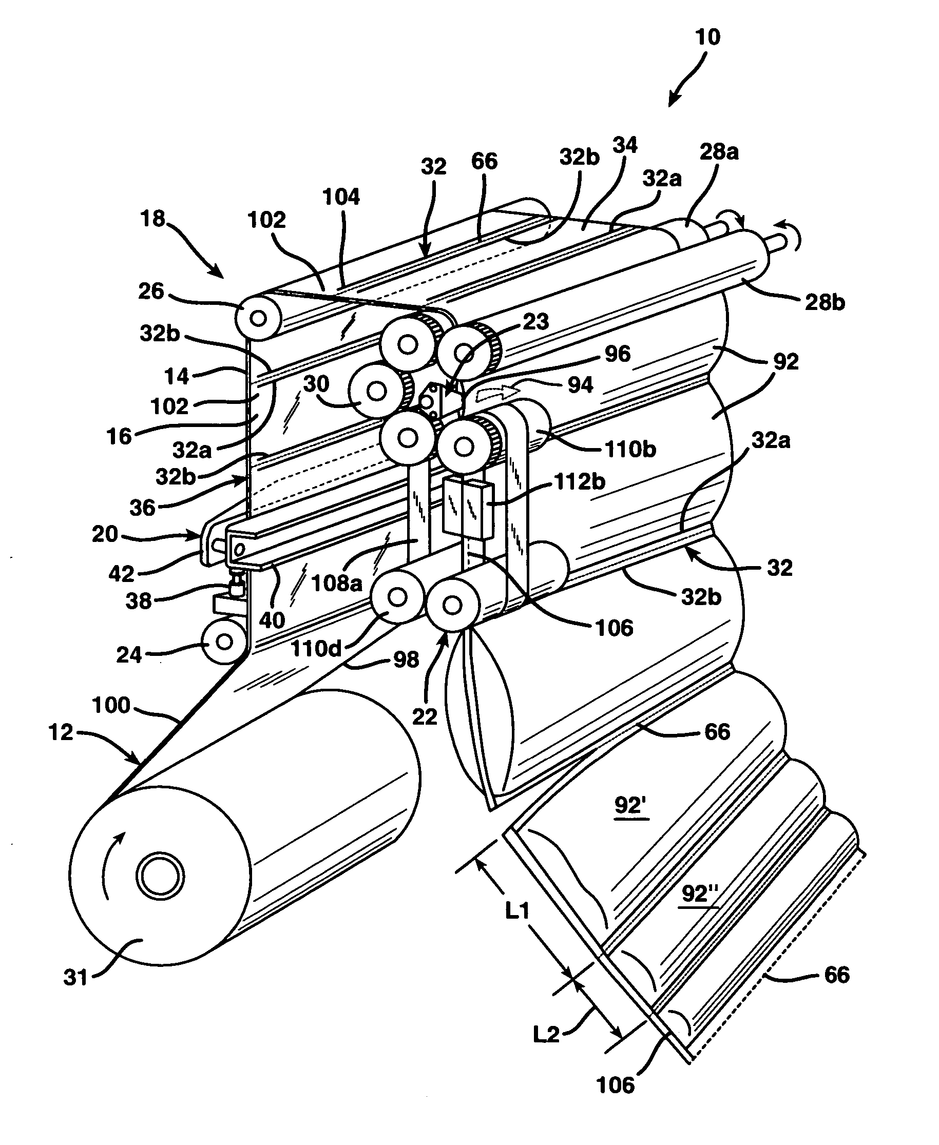
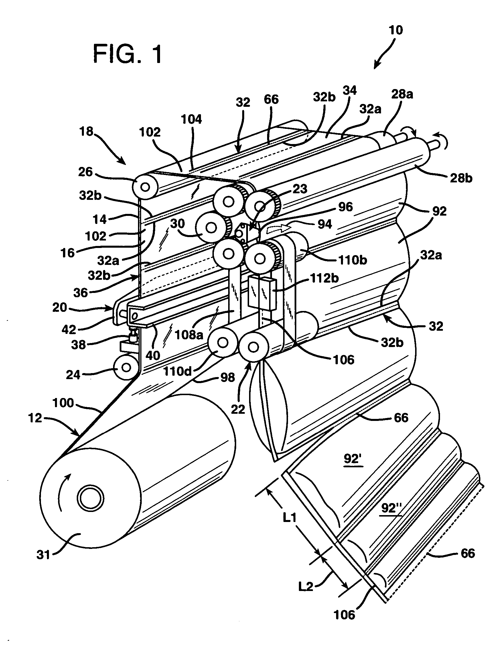
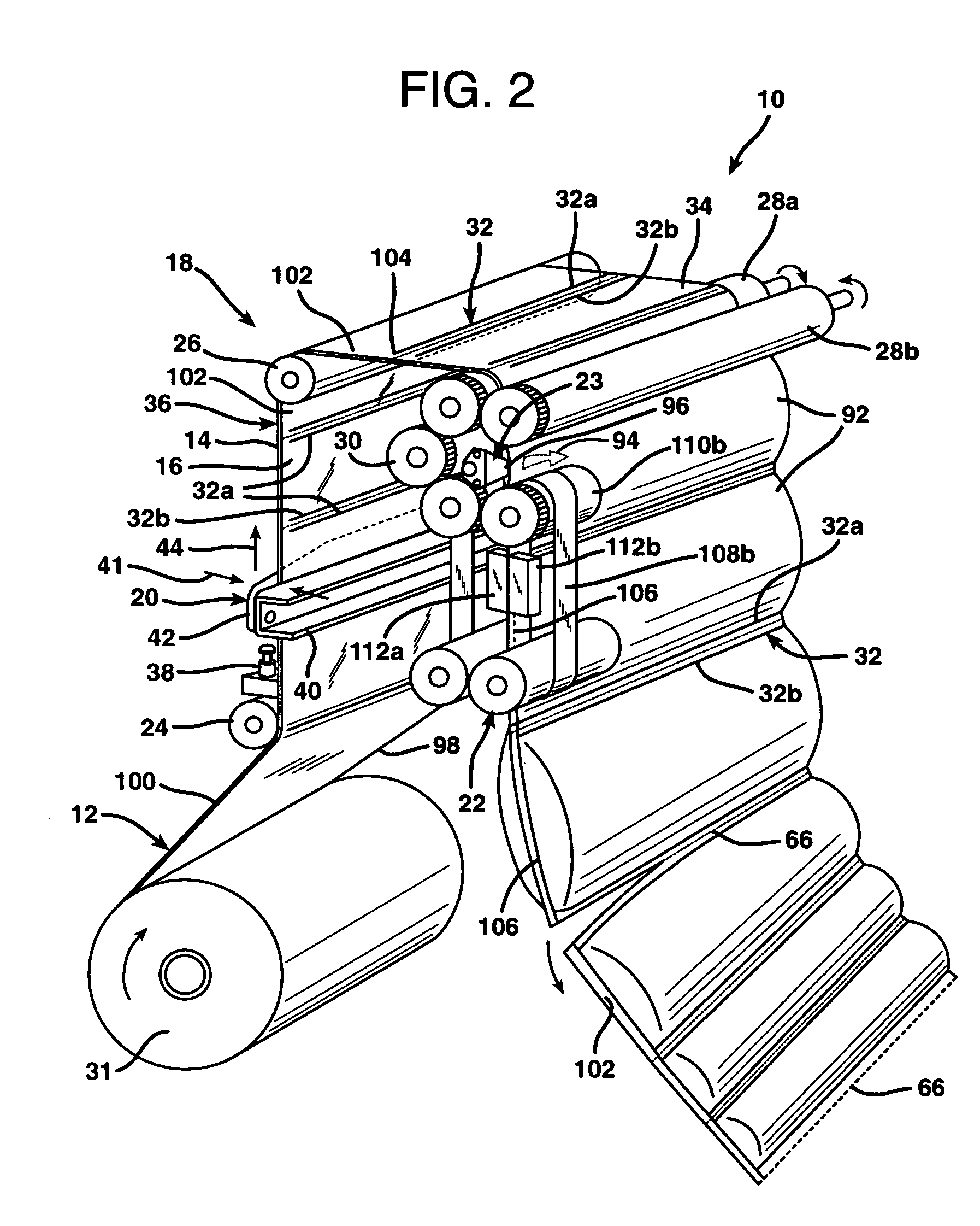
[0042]FIGS. 1-4 illustrate an apparatus 10 for making inflated containers from a film web 12 having two juxtaposed film plies 14 and 16. Such inflated containers may be used as cushions, e.g., for packaging and protecting articles during shipment and storage. Other uses for the inflated containers are also envisioned, e.g., as floatation devices or decorative articles. Apparatus 10 generally includes a conveying mechanism 18, a first sealing device 20, a second sealing device 22, and an inflation assembly 23.

[0043] Conveying mechanism 18 conveys film web 12 along a path of travel through apparatus 10 as shown. The “path of travel” (or “travel path”) of film web 12 simply refers to the route that the film web traverses while being conveyed through the apparatus, as indicated by the shape assumed by the film web due to the manipulation thereof by the conveying mechanism. Conveying mechanism 18 may include various conventional film-guide and film-drive devices as desired, such as guid...


PUM

PropertyMeasurementUnit
compressive forceaaaaaaaaaa
force of gravityaaaaaaaaaa
dimensionaaaaaaaaaa

Abstract

An apparatus for forming inflated containers from a film web having two juxtaposed film plies includes: a. a mechanism that conveys the film web along a path of travel; b. a first sealing device for producing one or more seals that bond the film plies together to form a container having at least one opening; c. an inflation assembly for inflating the container by directing a stream of gas into the opening thereof; and d. a second sealing device for sealing closed the opening of the inflated container.

Description

BACKGROUND OF THE INVENTION [0001] The present invention relates to inflated containers and, more particularly, to a simplified and improved apparatus and process for producing gas-inflated cushions for packaging. [0002] Various apparatus and methods for forming inflated cushions or pillows are known. Such inflated containers are used to package items, by wrapping the items in the cushions and placing the wrapped items in a shipping carton, or simply placing one or more inflated containers inside of a shipping carton along with an item to be shipped. The cushions protect the packaged item by absorbing impacts that may otherwise be fully transmitted to the packaged item during transit, and also restrict movement of the packaged item within the carton to further reduce the likelihood of damage to the item.[0003] Conventional machines for forming inflated cushions tend to be rather large, expensive and complex, and produce cushions at a rate which is slower than would be desired. While...

Claims


Application Information

Patent Timeline
Patent Type & Authority Applications(United States)
IPC IPC(8): B65B31/00
CPCB29C65/02B29C65/18B29C65/242B29C65/7457B29C65/7841B29C65/7873B29C65/7894B29C66/0342B29C66/20B29C66/232B29C66/244B29C66/3452B29C66/439B29C66/81457B29C66/83423B29C66/83543B29C66/8412B29C66/87443B29C66/91421B29C66/96B29C2793/0045B29K2023/06B29K2023/0608B29K2023/0616B29K2023/0625B29K2023/0633B29K2023/0641B29K2023/065B29K2023/083B29K2023/12B29K2025/00B29K2067/00B29K2069/00B29K2077/00B29K2101/12B29K2105/0085B29L2022/02B29L2031/7138B29L2031/751B31D5/0073B31D2205/0023B31D2205/0058B65B55/20B29C65/00B29C65/223B29C66/0044B29C66/8122B29K2827/18B29C65/305B29C66/9161B29C66/81427B29C66/8181B29C66/71B29C66/8221B29C66/8242B29C66/8246B29C66/1122B29C66/723B29K2025/06B29K2023/16B29K2023/10B29K2023/04
Inventor SPERRY, LAURENCE B.KANE, ERIC A.
Owner SEALED AIR U S
Learn More