
Portable cleaner

a vacuum cleaner and portable technology, applied in the field of portable vacuum cleaners, can solve the problems of dampening the vacuum efficiency and difficult to collect dust quickly, and achieve the effect of high vacuuming efficiency and convenient us

Inactive Publication Date: 2006-05-04
POON CHI WAI PATRICK
View PDF1 Cites 13 Cited by
  • Summary
  • Abstract
  • Description
  • Claims
  • Application Information

AI Technical Summary

Benefits of technology

[0003] An objective of the present invention is to overcome the disadvantages of existing vacuum cleaners for computer devices, especially for keyboards, and to provide an easy-to-use and portable vacuum cleaner with high vacuuming efficiency.
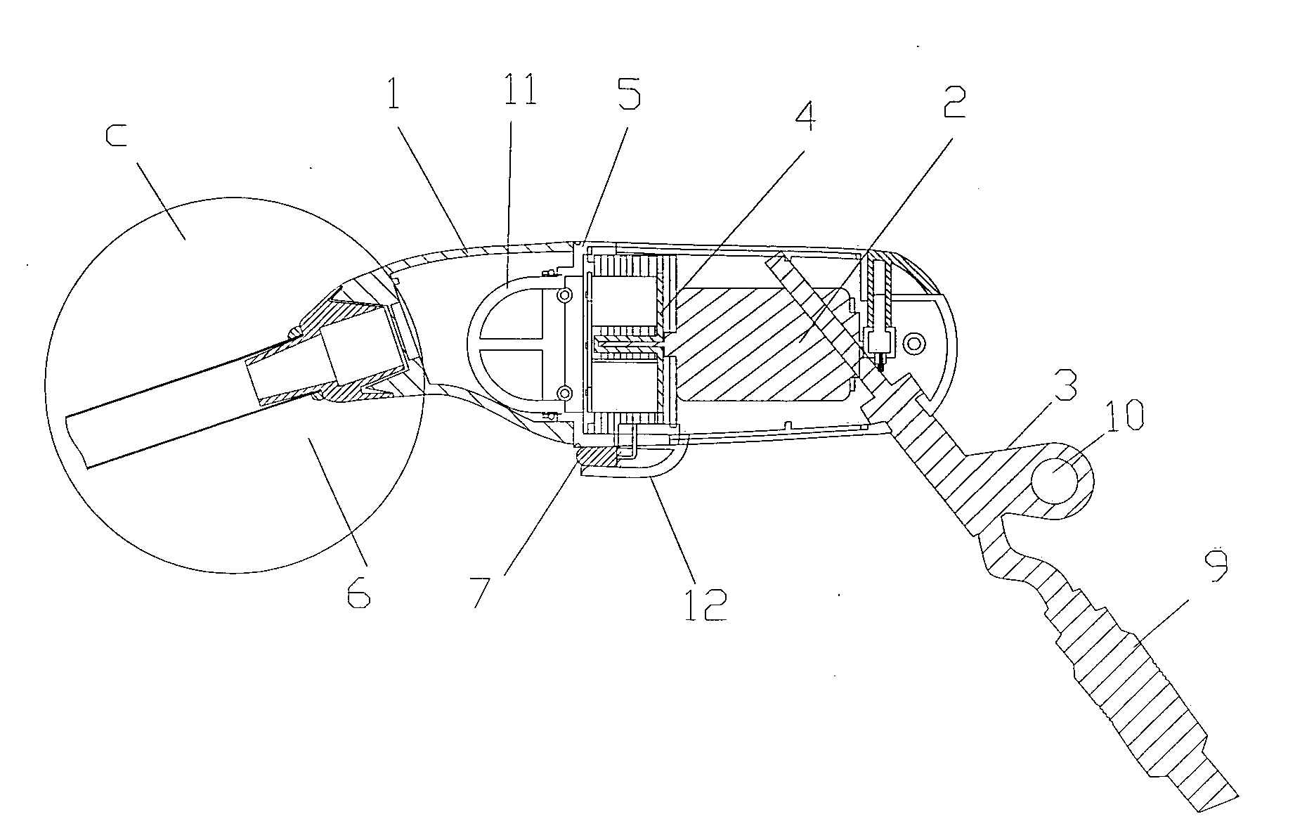
[0005] In this novel practical vacuum cleaner, the end-to-end joint between the power plug and USB interface of a computer allows power to be easily supplied to the vacuum. The head lamp at the lower part of the vacuum cleaner makes it easy to suck dust inside a computer or in dim light. Changing suction nozzles with different shapes based on requirements and the brush being on the external circle surface of the nozzle allows dust to be removed from the narrow crevices among components inside and outside the computer devices. Furthermore, the nozzle can reach these narrow crevices to suck dust. A hanging loop above the power cord makes it easy to store the vacuum cleaner near the computer devices. Therefore, this vacuum cleaner is a portable, handy, practical and highly efficient dust suction equipment for computer devices, and even for other instruments.

Problems solved by technology

However, the bulky dimension of this kind of vacuum cleaner makes it difficult to collect dust expediently.
Moreover, the narrow and deep crevices exist in many computer devices damper the vacuum efficiency.

Method used


Image

  • Portable cleaner
  • Portable cleaner

Examples


Embodiment Construction

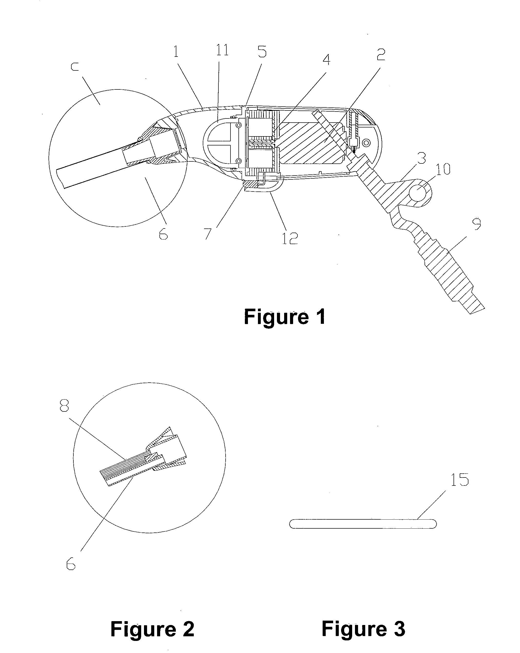
[0010] Referring to FIG. 1, the present novel portable vacuum cleaner includes a shell 1, an electrical motor 2 with proper input voltage and power to supply power to the vacuum cleaner, a power cord 3 with its power plug 9 having an end-to-end joint with UBS interface of a computer, an impeller 4, an airtight loop 5, a filter 11 and a suction nozzle 6. In order to vacuum dust inside a computer or in dim light, an indicator lamp base located below the external surface in the middle axial part of shell 1 can be used to install a light emitting diode (LED) head lamp 7 with relatively higher power. The disassembling connection between the suction nozzle 6 and the shell 1 makes it possible to change suction nozzles with different shapes based on the dusting requirements.

[0011] Referring to FIG. 2, a brush 8 has a distal end (not illustrated) which extends beyond the intake surface of a suction nozzle 6′. The nozzle 6′ is ; preferably in the form of three parallel cylindrical tubes. The...


PUM


Abstract

A novel portable vacuum cleaner comprising a shell, electric motor, power cord, impeller, airtight loop, filter and suction nozzle, is disclosed. The power plug may have an end-to-end joint with the Universal Serial Bus (USB) interface of the computer. A head lamp may be mounted below the external surface in the middle axial part of the shell. The cross-sectional shape of the suction nozzle shows an elongated thin pipe. A hanging loop is located above the power cord near the end of the shell. The vacuum design allows power to be easily supplied to the vacuum cleaner and dust suction inside the computer or in dim light and among crevices of components inside and outside the computers can be accomplished. Moreover, the vacuum cleaner can be easily stored beside the computer devices. Therefore, the vacuum cleaner is a portable, handy, practical and highly efficient dust suction equipment for computer devices.

Description

FIELD OF THE INVENTION [0001] The present invention relates to a portable vacuum cleaner used for dust removal from a computer and other devices. BACKGROUND OF THE INVENTION [0002] At the present time, vacuum cleaners for computer devices commonly use a battery as the power supply and are equipped with changeable suction nozzles of various shapes. However, the bulky dimension of this kind of vacuum cleaner makes it difficult to collect dust expediently. Moreover, the narrow and deep crevices exist in many computer devices damper the vacuum efficiency. It is therefore evident that there is a need for an improved vacuum cleaner for computer devices. SUMMARY OF THE INVENTION [0003] An objective of the present invention is to overcome the disadvantages of existing vacuum cleaners for computer devices, especially for keyboards, and to provide an easy-to-use and portable vacuum cleaner with high vacuuming efficiency. [0004] The portable vacuum cleaner in one embodiment of the present inve...

Claims


Application Information

Patent Timeline
IPC IPC(8): A47L5/24A47L9/00A47L9/28A47L9/30
CPCA47L5/24A47L9/0009A47L9/28A47L9/30
Inventor KUANG, ZHENXUAN
Owner POON CHI WAI PATRICK
Learn More