
System and method for qualitatively determining vehicle loading conditions

a technology for qualitatively determining and determining vehicle loading conditions, which is applied in the direction of process and machine control, transportation items, electric devices, etc., can solve the problems of more than 30%) changes in the chassis roll angle, and the difficulty of detection, and achieve the effect of relatively easy implementation and very accurate determination

Inactive Publication Date: 2006-04-27
FORD GLOBAL TECH LLC
View PDF99 Cites 44 Cited by
  • Summary
  • Abstract
  • Description
  • Claims
  • Application Information

AI Technical Summary

Benefits of technology

[0015] One advantage of the invention is that various entry conditions, i.e., when to update various vehicle parameters in response to the load and when to start the averaging process, may be determined. Such conditions may be implemented relatively easily on a vehicle using the output of existing sensors. Another advantage is that vehicle loading conditions can be detected and determined very accurately. Such Loading conditions (for example, roof loadings) are usually a fraction of the total vehicle mass (for example, 3% to 6% of the vehicle curb weight). Such conditions are difficult to be detected by using the methods involving longitudinal vehicle dynamics because there can be little influence in the vehicle's longitudinal dynamics but could cause large (for example, more than 30%) changes in. the chassis roll angle.

Problems solved by technology

Such conditions are difficult to be detected by using the methods involving longitudinal vehicle dynamics because there can be little influence in the vehicle's longitudinal dynamics but could cause large (for example, more than 30%) changes in. the chassis roll angle.

Method used


Image

  • System and method for qualitatively determining vehicle loading conditions
  • System and method for qualitatively determining vehicle loading conditions
  • System and method for qualitatively determining vehicle loading conditions

Examples


Embodiment Construction

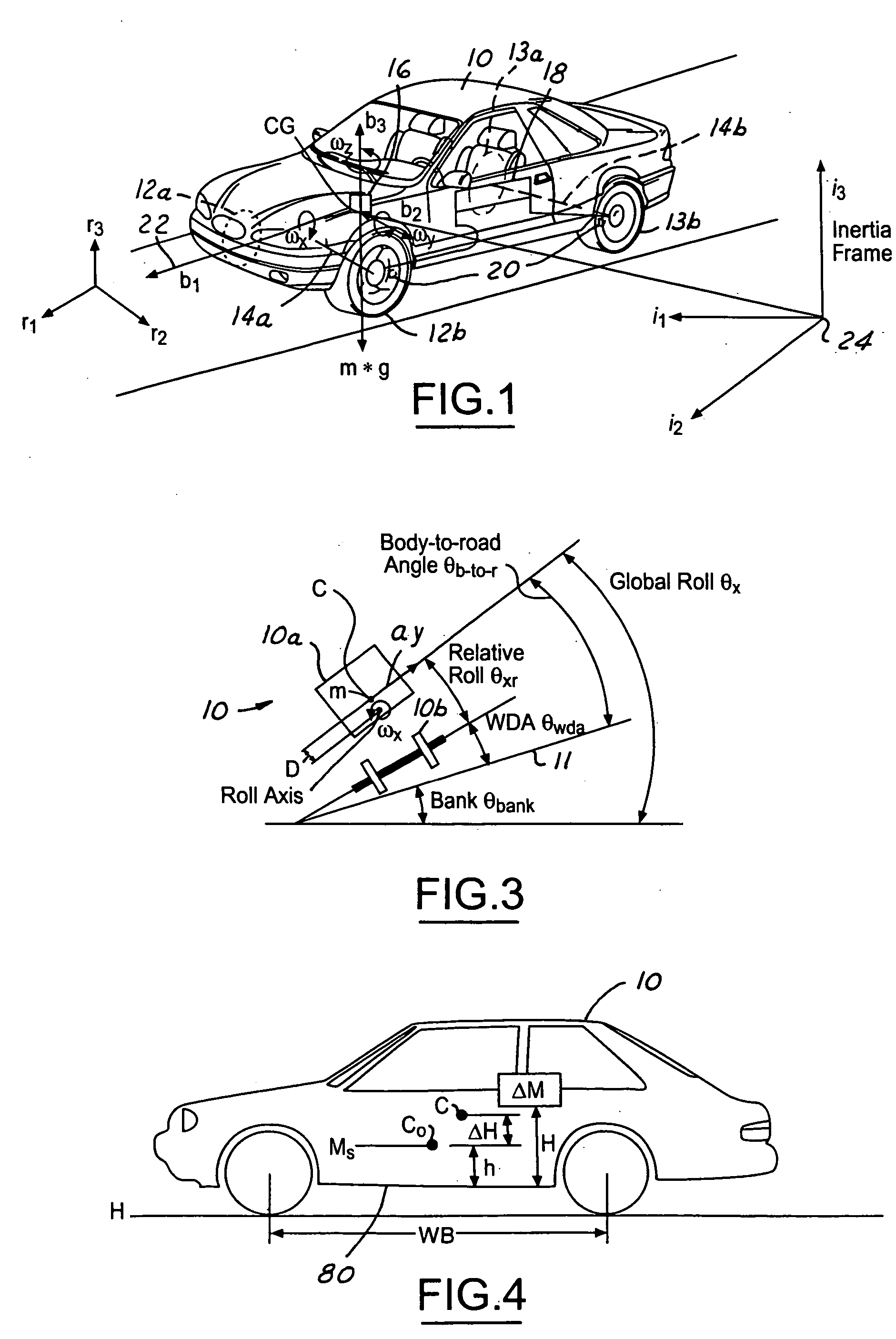
[0026] In the following figures, the same reference numerals will be used to identify the same components. The present invention may be used in conjunction with a rollover control system for a vehicle. The present invention may also be used with a deployment device such as an airbag or active roll bar. The present invention will be discussed below in terms of preferred embodiments relating to an automotive vehicle moving in a three-dimensional road terrain. The present invention is described with respect to determining an added mass and height of the mass. As will be described below, the added mass and height may not be directly determined, rather by adaptively updating roll condition parameter such as a roll gradient value, roll acceleration coefficient roll moment of inertia and / or a roll rate coefficient, the effects of added mass and the height may be included in those values. Such values may also be referred to as an “adaptive” roll gradient, an “adaptive” roll acceleration coe...


PUM


Abstract

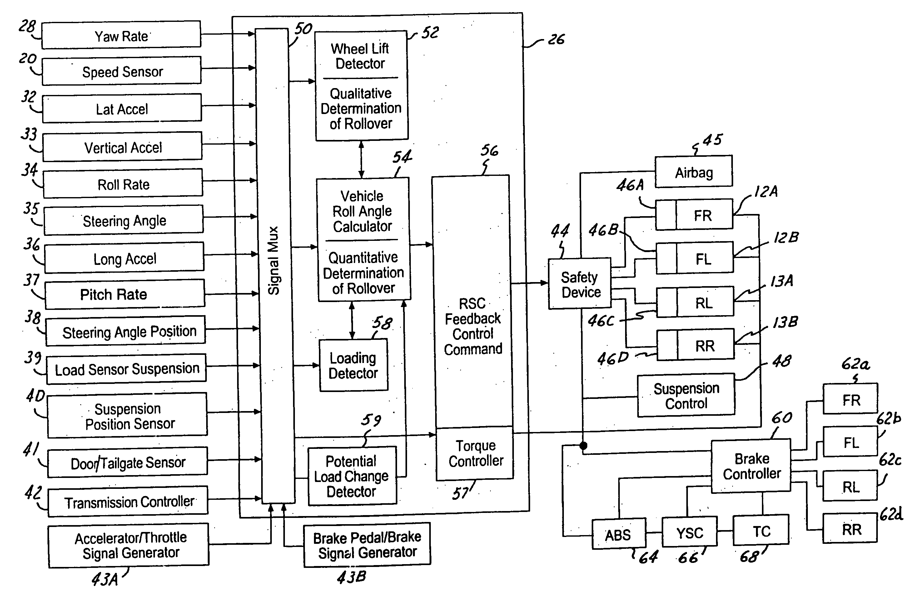
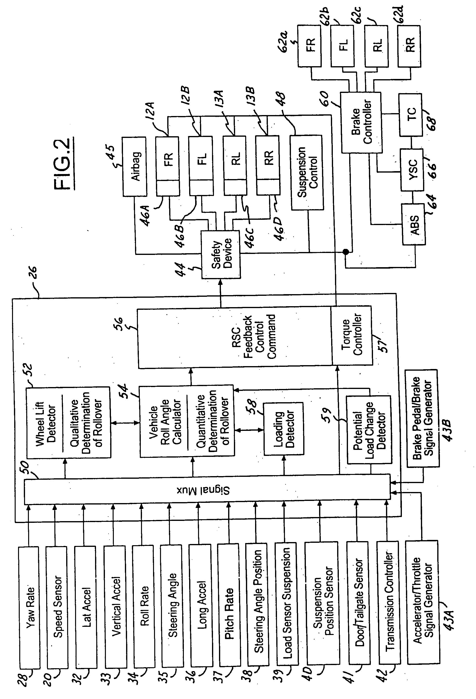
A control system (18) and method for an automotive vehicle (10) includes a controller (26) that determines whether or not a potential load change has occurred in a load change detector (59). A load change detector (59) may be coupled to various sensors to determine whether or not a change in load has occurred. If a change in load has occurred an adaptively determined roll condition parameter such as a roll acceleration coefficient, a roll rate parameter or a roll gradient may be reset. If a potential load change has not occurred, then a newly determined value for an adaptive roll condition may be included in a revised adaptive roll condition average. A safety device (44) may be controlled in response to the revised adaptive roll condition.

Description

RELATED APPLICATION [0001] The present application is a continuation-in-part of U.S. Patent Application (Attorney Docket 81044320 (FGT 1893 PA)) filed on Oct. 15, 2004, the disclosure of which is incorporated by reference herein.TECHNICAL FIELD [0002] The present invention relates generally to a control apparatus for controlling a system of an automotive vehicle in response to sensed dynamic behavior, and more specifically, to a method and apparatus for qualitatively determining a change in vehicle loading. BACKGROUND [0003] Recently, vehicle roll stability control (RSC) schemes, i.e., U.S. Pat. No. 6,324,446, have been proposed to address the issue of friction-induced rollovers. RSC system includes a variety of sensors sensing vehicle states and a controller that controls a distributed brake pressure to reduce a tire force so the net moment of the vehicle is counter to the roll direction. [0004] During an event causing the vehicle to roll, the vehicle body is subject to a roll mome...

Claims


Application Information

Patent Timeline
IPC IPC(8): G06F17/00B60R21/0132B60W10/18B60W10/20B60W10/22
CPCB60R21/0132B60T8/172B60T2230/03B60T2240/06B60W10/18B60W10/20B60W10/22B60W40/11B60W40/112B60W40/114B60G17/015B60T8/1755B60G2800/94B60G2800/9122B60G2800/92B60G2800/9124B60G2800/012B60T1/00
Inventor MESSIH, DAVIDLU, JIANBO
Owner FORD GLOBAL TECH LLC
Learn More