
Method and device to generate position profile in motion controller

a motion controller and position profile technology, applied in the direction of electric controllers, program control, instruments, etc., can solve the problems of large amount of variables to be stored, calculation errors may occur, and complicated calculation of coefficients according to initial conditions, so as to reduce the amount of calculations required and accurate calculation

Inactive Publication Date: 2006-04-27
STANZIONE & KIM
View PDF8 Cites 7 Cited by
  • Summary
  • Abstract
  • Description
  • Claims
  • Application Information

AI Technical Summary

Benefits of technology

"The present invention provides a device and method for generating a position profile in a motion controller that can accurately calculate the position and reduce the amount of calculations required. The device includes a pattern coefficient generator to generate pattern and time coefficients of a position pattern, a contour generator to generate a pattern polynomial to define a contour of each section of the position pattern, and a dual filter to selectively activate one of a plurality of filters. The method includes selecting one of a plurality of position patterns, comparing an initial velocity of the position pattern with a reference velocity, selecting one of a plurality of position pattern groups, and activating one of a plurality of filters. The technical effects of the invention include improved accuracy and efficiency in generating position profiles in motion controllers."

Problems solved by technology

However, this method requires a large amount of variables to be stored for calculation in the integration procedure.
It is also difficult for this method to implement asymmetrical acceleration / deceleration, and calculation errors may occur.
However, the conventional polynomial-based method requires a large number of coefficients for defining polynomials according to initial conditions, so that the calculation of the coefficients according to initial conditions is complicated, and a large amount of real-time calculation is needed.

Method used


Image

  • Method and device to generate position profile in motion controller
  • Method and device to generate position profile in motion controller
  • Method and device to generate position profile in motion controller

Examples


Embodiment Construction

[0048] Reference will now be made in detail to the embodiments of the present general inventive concept, examples of which are illustrated in the accompanying drawings, wherein like reference numerals refer to the like elements throughout. The embodiments are described below to explain the present general inventive concept by referring to the figures.

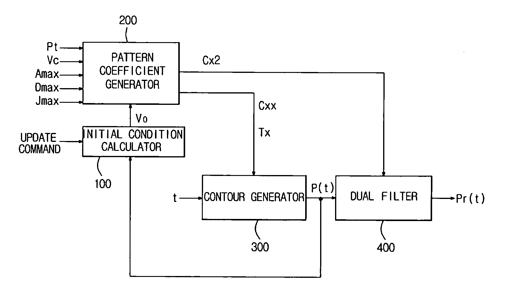
[0049]FIG. 3 is a schematic diagram illustrating how a position profile is generated from a position pattern according to an embodiment of the present general inventive concept, and FIG. 4 is a block diagram of a position profile generation device in a motion controller according to an embodiment of the present general inventive concept.

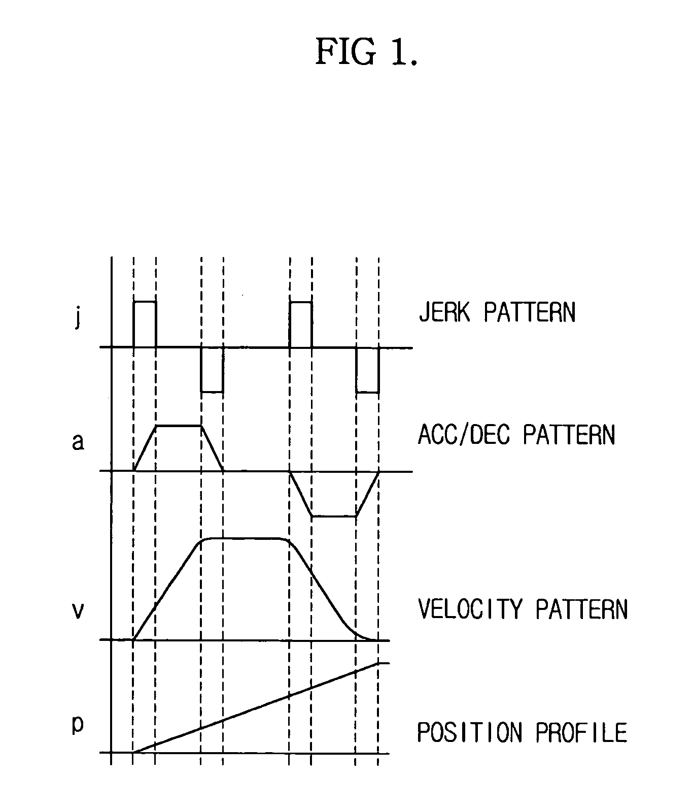
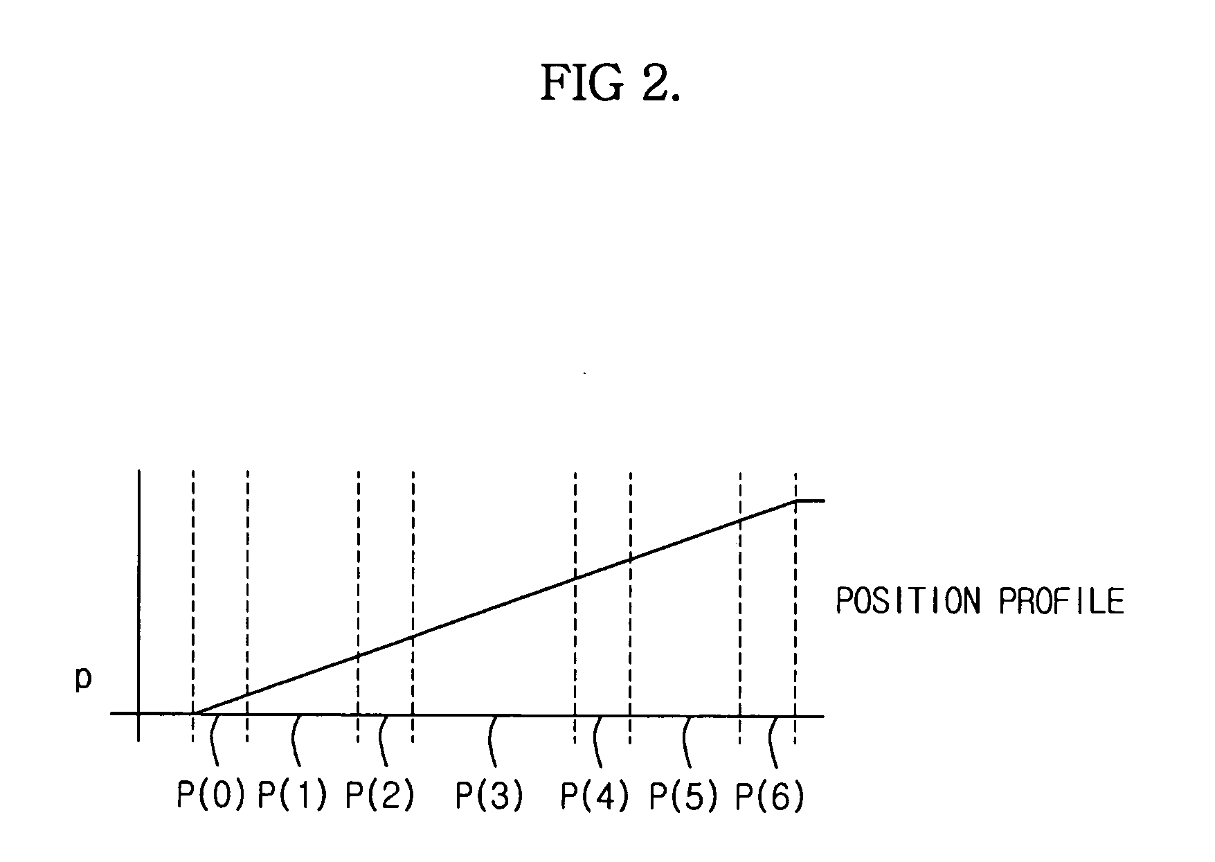
[0050] The present general inventive concept provides a method of generating a position profile by passing position patterns selected based on initial conditions through a dual filter. A position pattern is defined based on velocity change as time passes. Specifically, a position pattern may include, f...


PUM


Abstract

A method of and apparatus to generate a position profile using lower-order polynomials. The device includes a pattern coefficient generator to generate pattern and time coefficients of a position pattern that is classified by velocity change, a contour generator to generate a pattern polynomial to define a contour of each section of the position pattern using the generated pattern and time coefficients, and a dual filter for generating a position profile by selectively activating one of a plurality of filters, which receive the pattern polynomial generated by the contour generator. The device uses lower-order polynomials and a small number of coefficients, thereby reducing the number of calculations required in the procedure to generate the position profile. The device generates a seamless and smooth position profile by preventing switching errors due to the difference between filter sizes.

Description

CROSS-REFERENCE TO RELATED APPLICATIONS [0001] This application claims the benefit of Korean Patent Application No. 2004-85041, filed on Oct. 22, 2004 in the Korean Intellectual Property Office, the disclosure of which is incorporated herein in its entirety and by reference. BACKGROUND OF THE INVENTION [0002] 1. Field of the Invention [0003] The present general inventive concept relates to a method and device to generate a position profile using lower-order polynomials in a motion controller. [0004] 2. Description of the Related Art [0005] An industrial articulated robot moves a work subject to a target position by rotating and moving its joints, and includes a servomotor as a drive source for moving each joint. [0006] A motion controller generates a position profile using an input command and transfers it to a servo controller. The servo controller then controls the servomotor according to the position profile to move the work subject to the target position. The position profile is...

Claims


Application Information

Patent Timeline
Patent Type & Authority Applications(United States)
IPC IPC(8): G06F19/00
CPCG05B19/4103G05B2219/34122G05B2219/34142B25J9/16
Inventor HA, JUNG IK
Owner STANZIONE & KIM
Learn More