
Illumination device for vehicles and method for controlling an illumination device for vehicles

Inactive Publication Date: 2006-04-20
VOLKSWAGEN AG
View PDF15 Cites 8 Cited by
  • Summary
  • Abstract
  • Description
  • Claims
  • Application Information

AI Technical Summary

Benefits of technology

[0009] It is thus the object of the present invention to provide an illumination device for vehicles and / or a method for controlling an illumination device for vehicles of the aforementioned type, which can produce very small modifications in the brightness of the light-emitting diode over a large brightness range, or at least in a part of that range.

Problems solved by technology

A disadvantage of conventional controls of light-emitting diodes by means of the duty cycle of the pulse-width modulated clock signal is that the resolution of the modification in brightness, in particular at low levels of brightness, is too low.
Should the light-emitting diode not only perform two different illumination functions at different levels of brightness, but modify the brightness of one or several of the respective illumination functions with a very fine resolution, then the step sizes of known control devices are inadequate for light-emitting diodes.

Method used


Image

  • Illumination device for vehicles and method for controlling an illumination device for vehicles
  • Illumination device for vehicles and method for controlling an illumination device for vehicles
  • Illumination device for vehicles and method for controlling an illumination device for vehicles

Examples


Embodiment Construction

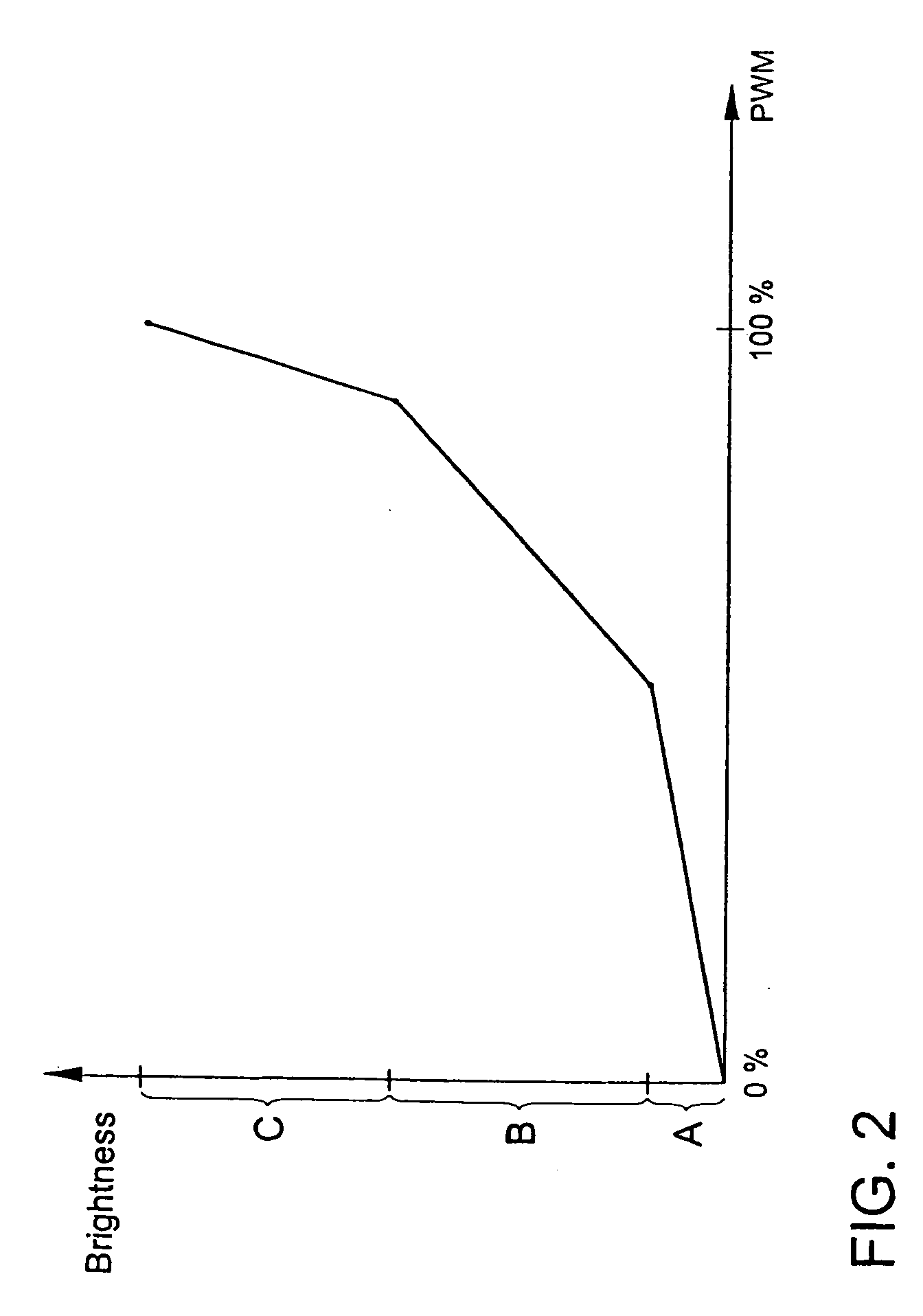
[0024] The illumination device comprises a light-emitting diode 3 or an array with a plurality of light-emitting diodes. The light-emitting diode 3 is controlled via a known light control unit 1. This light control unit 1 receives a value for the desired brightness via a vehicle bus 5. Based on this value, the light control unit 1 generates a pulse-width modulated clock signal, whose duty cycle corresponds with the value of the desired brightness. During this process the light control unit 1 can take into account the brightness characteristic, shown in FIG. 2, of the illumination device. The pulse-width modulated clock signal PWM is transmitted to the circuit 2. Further, a control signal S is transmitted to the circuit 2. In the illustrated embodiment the control signal S is also transmitted by the light control unit 1.

[0025] In the circuit 2, different protective resistors R1, R2 and R3 are provided in parallel for the light-emitting diode 3. Associated with each of the protective...


PUM


Abstract

The present invention relates to an illumination device for vehicles with at least light-emitting diode (3) and a light control unit (1), wherein the light control unit (1) is connected to the at least one light-emitting diode (3) and a pulse-width modulated clock signal (PWM) can be generated and transmitted to the at least one light-emitting diode (3) with the light control unit (1). The illumination device for vehicles according to the invention comprises a circuit (2) arranged between the light control unit (1) and the at least one light-emitting diode (3), with which, depending on the control signal (S), the pulse-width modulated clock signal (PWM) can be fed via different resistors (R1, R2, R3) to the at least one light-emitting diode (3). The present invention further relates to a method for controlling an illumination device for vehicles with at least one light-emitting diode (3) and a light control unit (1). In the method according to the invention the light control unit (1) generates a pulse-width modulated clock signal (PWM), which the light control unit (1) transmits to a circuit (2). The circuit receives a control signal (S) and, depending on the control signal (S), feeds the pulse-width modulated clock signal to the at least one light-emitting diode (3) via different resistors (R1, R2, R3).

Description

BACKGROUND OF THE INVENTION [0001] 1. Field of the Invention [0002] The present invention relates to an illumination device for vehicles with at least one light-emitting diode and one light control unit, wherein the light control unit is connected to the at least one light-emitting diode and a pulse-width modulated clock signal can be generated and transmitted to the at least one light-emitting diode with the light control unit. Further, the invention relates to a method for controlling an illumination device for vehicles with at least one light-emitting diode and one light control unit. [0003] 2. Description of the Related Art [0004] Light-emitting diodes are being used increasingly as light sources in vehicle lights. In particular, the light-emitting diode is becoming increasingly significant in the area of the exterior illumination of motor vehicles. These light sources have the advantage over conventional incandescent bulbs that they exhibit a longer lifetime and increased produ...

Claims


Application Information

Patent Timeline
IPC IPC(8): B60Q1/10H05B44/00
CPCH05B33/0845Y10S362/80H05B45/10
Inventor BUHR, CHRISTOPHBOTTCHER, ANJA
Owner VOLKSWAGEN AG
Learn More