
Biaxial actuator and method of manufacturing the same

a technology of biaxial actuators and actuators, which is applied in the direction of electrostatic generators/motors, instruments, electrostatic motors, etc., can solve the problems of increasing the screen size of the display device, the limitation of increasing the driving speed and the driving angle of biaxial actuators, and the difficulty of conventional actuators designed for resonant driving to operate at a non-resonant frequency, etc., to achieve high driving angle, high driving force, and easy manufacturing

Inactive Publication Date: 2006-04-20
SAMSUNG ELECTRONICS CO LTD
View PDF7 Cites 64 Cited by
  • Summary
  • Abstract
  • Description
  • Claims
  • Application Information

AI Technical Summary

Benefits of technology

[0010] The present invention may also provide a biaxial actuator having a high driving force and a high driving angle, and a method of manufacturing the biaxial actuator.
[0011] The present invention may also provide a biaxial actuator, which can be manufactured easily, and a method of manufacturing the biaxial actuator.

Problems solved by technology

Also, as the driving angle of the micro mirror increases, the screen size of the display device increases.
However, since the driving speed and the driving angle of the micro mirror are in a trade-off relation, there is a limitation in increasing both the driving speed and the driving angle of the biaxial actuator.
Conventional actuators designed for resonant driving are hard to operate at a non-resonant frequency.

Method used


Image

  • Biaxial actuator and method of manufacturing the same
  • Biaxial actuator and method of manufacturing the same
  • Biaxial actuator and method of manufacturing the same

Examples


first embodiment

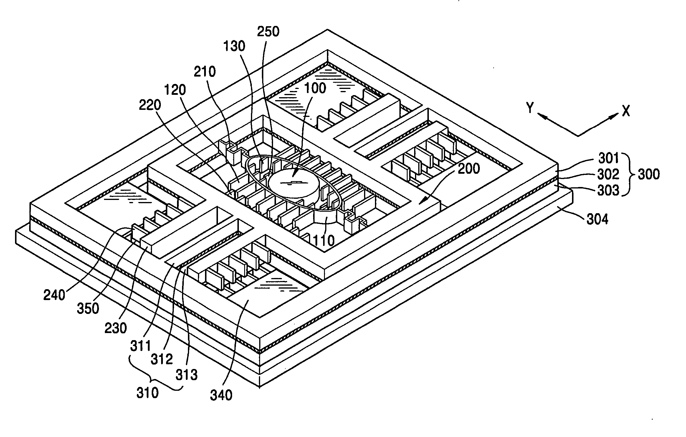
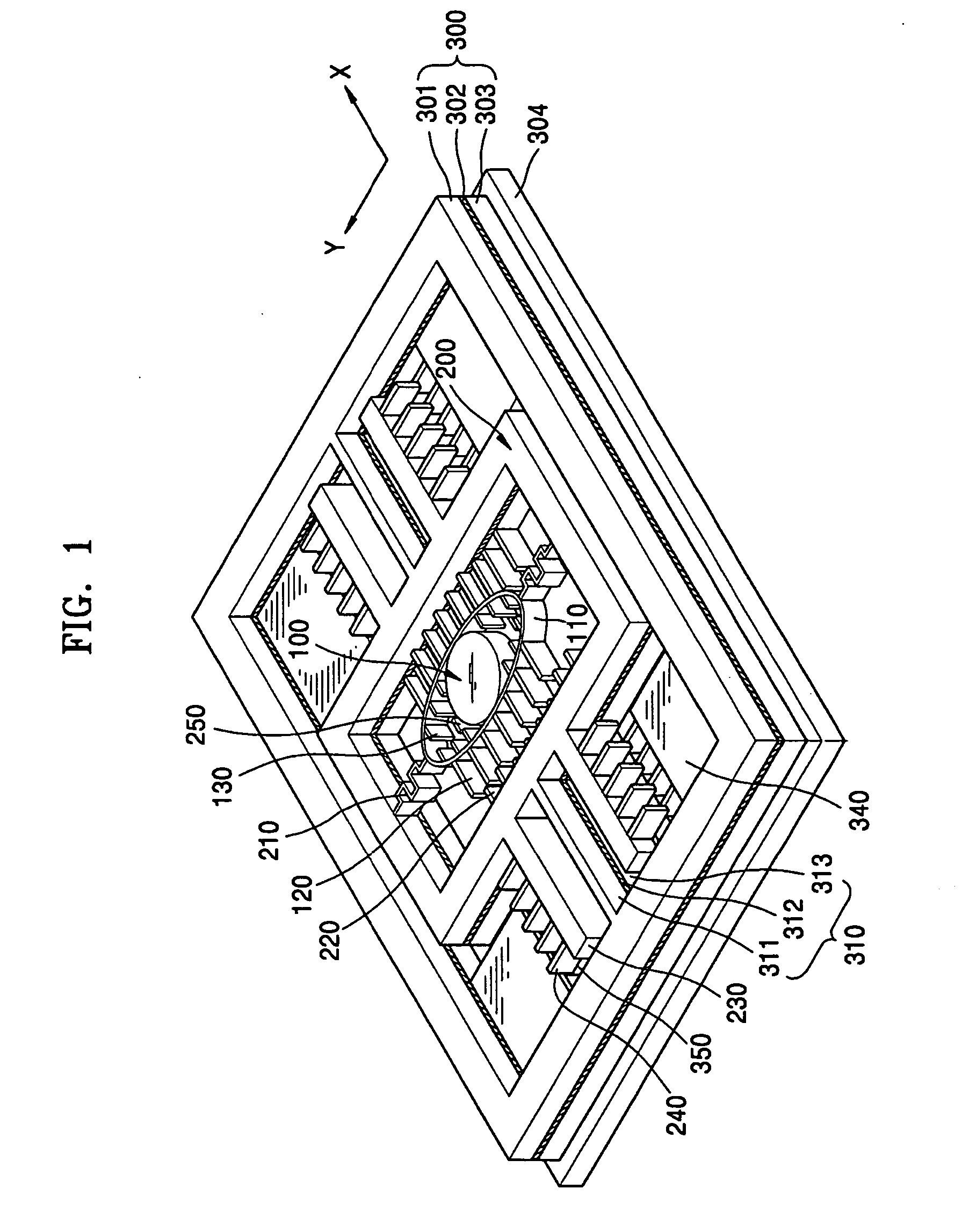
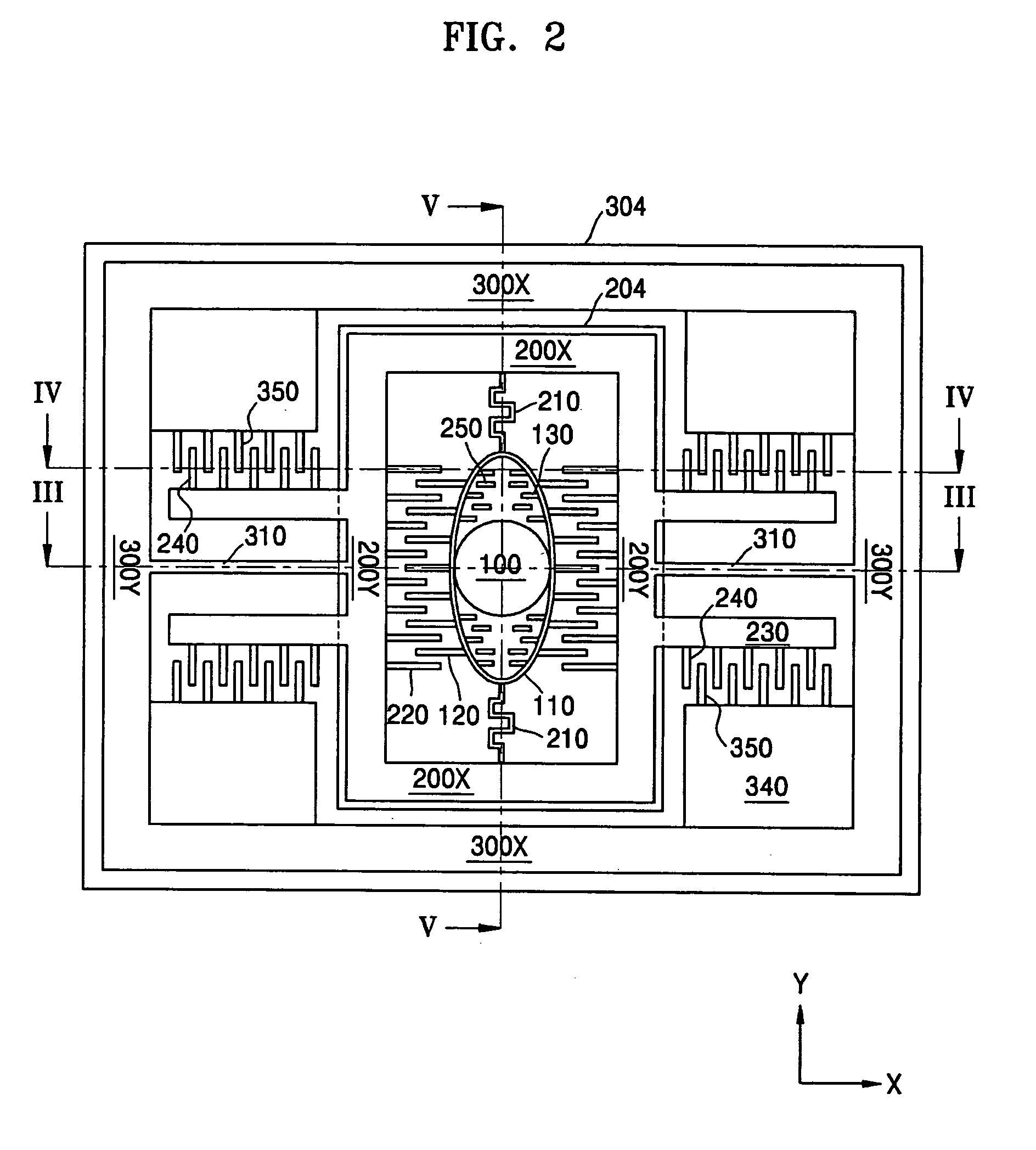
[0041]FIG. 1 is a schematic perspective view of a biaxial actuator according to the present invention. FIG. 2 is a plan view of the biaxial actuator of FIG. 1. FIGS. 3 through 5 are sectional views respectively taken along lines III-III, IVIV, and V-V of FIG. 2.

[0042] Referring to FIGS. 1 and 2, a stage unit may include a stage 100 that has a mirror (not shown) formed on a surface thereof, and a connecting part 110. The stage 100 may be a circular plate with a minimum area for light reflection. The connecting part 110 may be an oval band, and the stage 100 may be connected to an inner circumferential surface in a direction of the shorter diameter of the connecting part 110. The reason why such a circular stage 100 may be used is to reduce the load of the stage 100 and increase a driving force.

[0043] The connecting part 110 may be supported by a first support unit including first torsion springs 210 and a rectangular moving frame 200 such that the connecting part 110 can seesaw in a...

second embodiment

[0057]FIG. 8 is a sectional view of a biaxial actuator according to the present invention. The actuator may be structured such that the third driving comb electrodes 130, the third fixed comb electrodes 250, the first base 204, and the conductive layer 206 that electrically connects between the first fixed comb electrodes 220 and the third fixed comb electrodes 250 are removed from the actuator shown in FIG. 4.

[0058] An actuator according to a third another embodiment of the present invention shown in FIGS. 9 and 10 further includes a driving unit that is disposed on a stage unit and drives the stage in two directions.

[0059]FIGS. 9 and 10 are schematic sectional views of the actuator according to a third embodiment of the present invention. The same elements as those in the first embodiment may be given the same reference numerals, and a detailed explanation thereof will not be given.

[0060] Referring to FIGS. 2, 9, and 10, on the basis of a first level on which a stage unit and dr...


PUM


Abstract

Provided are a biaxial actuator and a method of manufacturing the same. The biaxial actuator includes: a stage unit seesawing in a first direction; a first support unit supporting the stage unit; a stage unit driving unit including first driving comb electrodes outwardly extending from opposite sides of the stage unit in the first direction, and first fixed comb electrodes extending from the first support unit facing the first driving comb electrodes such that the first driving and fixed comb electrodes alternate with each other; a second support unit supporting the first support unit such that the first support unit seesaws in a second direction perpendicular to the first direction; and a first support unit driving unit including second driving comb electrodes installed at the first support unit, and second fixed comb electrodes corresponding to the second driving comb electrodes, wherein the first and second driving comb electrodes and the stage unit are formed at a first level, and the first and second fixed comb electrodes are formed at a second level lower than the first level such that the first and second fixed comb electrodes do not overlap with the first and second driving comb electrodes at a vertical plane.

Description

BACKGROUND OF THE DISCLOSURE [0001] This application claims the priority of Korean Patent Application No. 10-2004-0083537, filed on Oct. 19, 2004, in the Korean Intellectual Property Office, the disclosure of which is incorporated herein in its entirety by reference. [0002] 1. Field of the Disclosure [0003] The disclosure relates to a biaxial micro-electro-mechanical system (MEMS) actuator and a method of manufacturing the same, and more particularly to a biaxial actuator for seesaw driving in two directions and a method of manufacturing the same. [0004] 2. Description of the Related Art [0005] Optical scanners including biaxial actuators can be used for large displays. The driving speed of a biaxial actuator relates to the resolution of a display device, and the driving angle of the biaxial actuator relates to the screen size of the display device. That is, as the driving speed of a micro mirror increases, resolution is improved. Also, as the driving angle of the micro mirror incre...

Claims


Application Information

Patent Timeline
Patent Type & Authority Applications(United States)
IPC IPC(8): G02B26/08G02B26/00H02N1/00
CPCG02B26/0841H02N1/008B81B7/02
Inventor KO, YOUNG-CHULLEE, JIN-HOCHO, JIN-WOOJEONG, HYUN-KU
Owner SAMSUNG ELECTRONICS CO LTD
Learn More