
Device and method for delivery of long wavelength laser energy to a tissue site

a long wavelength laser and tissue technology, applied in the field of laser energy delivery devices, can solve the problems of reducing the amount of laser energy reaching the target tissue, ablating or vaporizing the tissue, and wasting a substantial amount of laser energy, and achieve the effect of facilitating the placement of the open distal end

Inactive Publication Date: 2006-04-13
TRIMEDYNE
View PDF6 Cites 28 Cited by
  • Summary
  • Abstract
  • Description
  • Claims
  • Application Information

AI Technical Summary

Benefits of technology

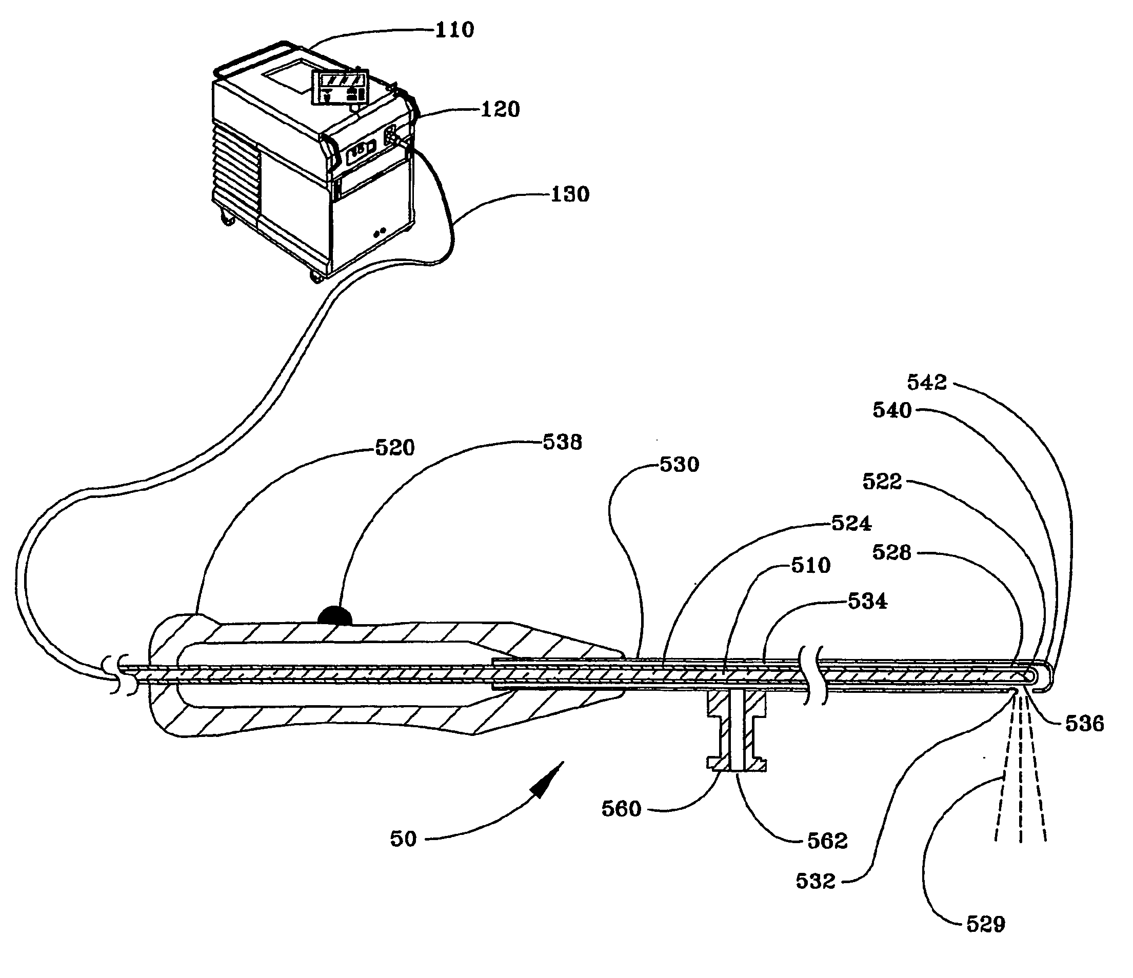
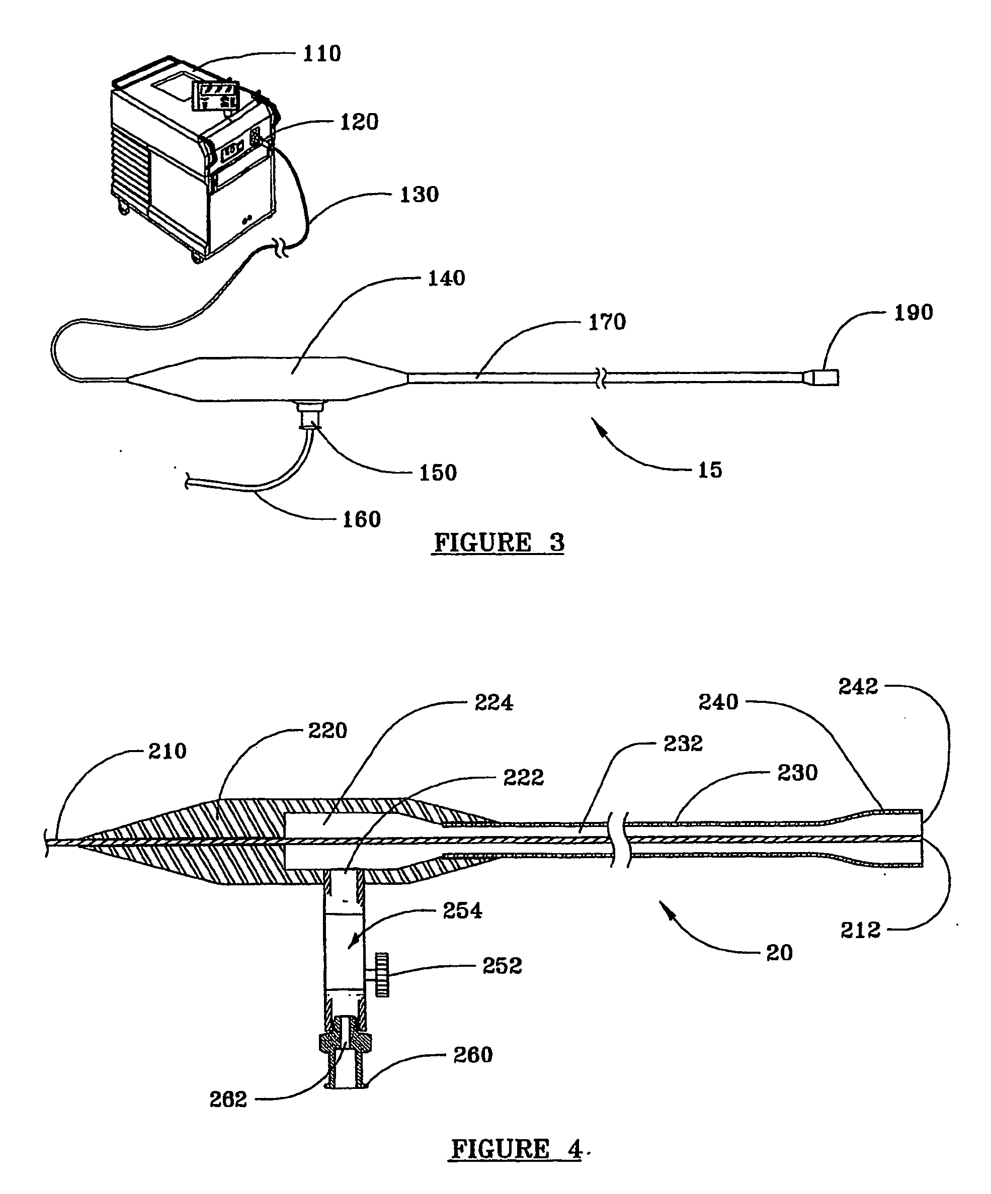
"The present invention is a laser energy delivery device that can effectively deliver laser energy to tissue in an aqueous medium with minimal loss of energy. The device includes an elongate hollow sheath with an open aperture at the distal end and a closed proximal end. The sheath has a gas inlet port and a gas outlet port that serves as the open aperture. The open aperture can be substantially coaxial with a laser energy conduit within the sheath or offset from the longitudinal axis therefrom. The device also includes a handpiece at the proximal end of the sheath for easy handling and placement. The distal end of the sheath can be bent at an angle from the axis of the handpiece to facilitate placement against the tissue that is to be irradiated by laser energy. The device is suitable for delivering relatively long wavelength laser energy to a tissue in an aqueous medium. When an aqueous liquid is present at the tissue site, carbon dioxide or other biocompatible gas is infused into the sheath or handpiece and through the passageway defined between the optical fiber and the sheath, creating a substantially liquid-free region between the distal end of the energy conduit and the tissue. This enables a substantially greater portion of the laser energy to be utilized to vaporize the target tissue compared with irradiation through an aqueous liquid that necessarily absorbs and dissipates at least some of the laser energy."

Problems solved by technology

When exposed to such long wavelength laser energy, the water in the tissue is rapidly heated and converted to steam, causing ablation or vaporization of the tissue.
However, when water, saline, or other aqueous liquid is infused through the endoscope to provide a clear field of view of the tissue inside a duct, body cavity, hollow organ, or surgically created passageway, via the fiber optical viewing device, a substantial amount of the laser energy is wasted.
However, as the steam bubble collapses between pulses of laser energy, liquid flows back into the space between the distal end of the optical fiber and the target tissue, requiring some of the laser energy to again be consumed in recreating the steam bubble between the optical fiber and the tissue, diminishing the amount of laser energy reaching the target tissue.
As a result, the laser procedure never became popular and is presently used only infrequently.

Method used


Image

  • Device and method for delivery of long wavelength laser energy to a tissue site
  • Device and method for delivery of long wavelength laser energy to a tissue site
  • Device and method for delivery of long wavelength laser energy to a tissue site

Examples


Embodiment Construction

[0025] while this invention is susceptible of embodiment in many different forms, there are shown in the drawings and are described in detail herein specific embodiments of the invention, with the understanding that the present disclosure is an exemplification of the principles of the invention and is not limited to the specific embodiments illustrated.

[0026] In the device and method of present invention, air or another biologically compatible gas, such as argon, carbon dioxide, helium, nitrogen, or a mixture thereof, preferably carbon dioxide, is infused into a sheath disposed over a laser energy conduit such as an optical fiber or optical wave guide, and displaces liquid at the distal end of the sheath. Light energy from a laser that is optically coupled to the laser energy conduit is emitted at a wavelength of at least about 1,300 nanometers (referred to herein as long wavelength laser energy, or LW laser energy) from the distal end of the laser energy conduit. The entire sheath...


PUM


Abstract

A laser energy delivery device is provided that is suitable for irradiating a body tissue with relatively long wavelength laser energy in the presence of an aqueous liquid without significant absorption of the laser energy by the liquid. The device includes an elongate hollow sheath that has an open aperture at its distal end portion and closed at its proximal end, a laser energy conduit such as an optical fiber or hollow wave guide, within the sheath, the distal end of the conduit being disposed near the open aperture at the distal end portion of the sheath, and the proximal end of the conduit being adapted for connection to a source of long wavelength laser energy. The sheath also includes an inlet port, spaced from the proximal end of the sheath, and adapted to receive and deliver a biologically compatible gas through the sheath to a body tissue site in contact with the open distal end of the sheath. In use, the open aperture at the distal end portion of the sheath is positioned in contact with a body tissue site. Gas, such as carbon dioxide, infused through the sheath displaces an aqueous liquid from the region between the distal end portion of the sheath and the tissue. Laser energy emitted from the distal end portion of the conduit passes through the substantially liquid-free region at the distal end of the sheath and impinges on the tissue to be irradiated. The laser energy can be used to ablate, vaporize, coagulate or shrink tissue at the target zone without interference from aqueous liquids, which tend to absorb relatively large amounts of long wavelength laser energy and reduce the efficiency of tissue ablation.

Description

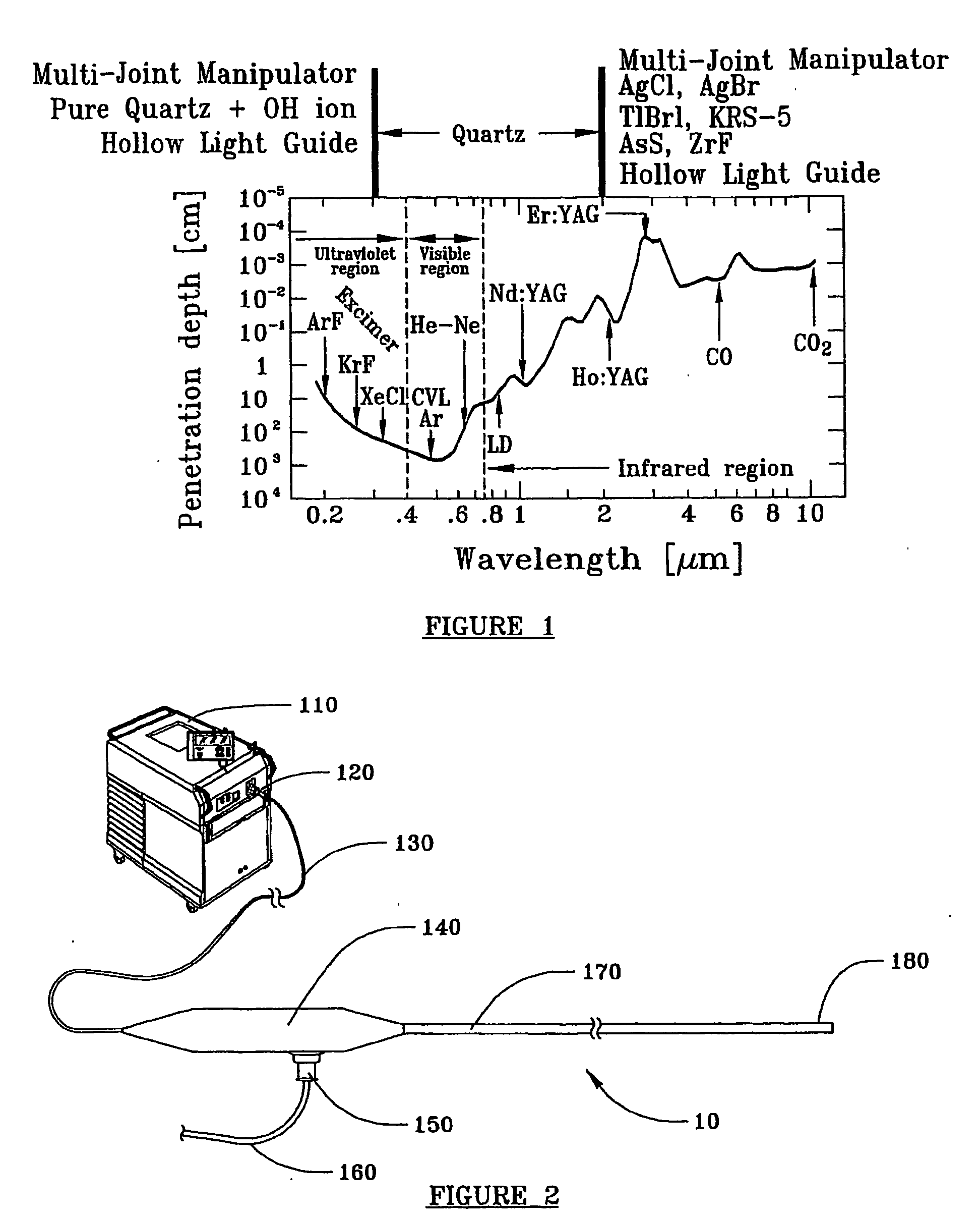
CROSS-REFERENCE TO RELATED APPLICATION [0001] This application is a continuation-in-part of copending U.S. patent application Ser. No. 10 / 324,897, filed on Dec. 20, 2002.FIELD OF THE INVENTION [0002] The present invention relates to laser energy delivery devices and their method of use in an aqueous environment. More particularly, the invention relates to laser energy delivery devices useful for delivering laser energy at wavelengths of about 1,300 to 11,000 nanometers, to a body tissue site with reduced interference from surrounding aqueous fluid media. BACKGROUND OF THE INVENTION [0003] Lasers that emit light energy at wavelengths in the range of about 1,300 to about 11,000 nanometers (long wavelength or “LW” laser energy) are excellent vaporizers of tissue, since their energy is highly absorbed by water, a major constituent of mammalian tissue. When exposed to such long wavelength laser energy, the water in the tissue is rapidly heated and converted to steam, causing ablation or ...

Claims


Application Information

Patent Timeline
Patent Type & Authority Applications(United States)
IPC IPC(8): G02B6/42A61B1/06A61B17/00A61B18/00A61B18/20A61B18/22
CPCA61B18/201A61B18/22A61B2017/00274A61B2018/00547A61B2218/006A61B2018/00625A61B2018/00577
Inventor LOEB, MARVIN P.
Owner TRIMEDYNE
Learn More