Phase-change optical recording media and optical recording-reproducing apparatus

a technology of optical recording media and optical recording recording equipment, which is applied in the direction of mechanical recording, record information storage, instruments, etc., can solve the problems of information in a certain track deteriorating, so-called cross-erase problems, and errors in the stage of converting signals into digital data

Inactive Publication Date: 2006-04-13
KK TOSHIBA
View PDF9 Cites 9 Cited by
  • Summary
  • Abstract
  • Description
  • Claims
  • Application Information

AI Technical Summary

Benefits of technology

[0026] An optical recording media according to an aspect of the present invention comprises: two or more information layers, at least one of the information layers including a writable recording film, at least one information layer having protrusions and recesses that permit tracking and at least another one information layer being substantially flat.

Problems solved by technology

However, where the recording marks are close to each other, the obtained signals have lowered amplitude, with the result that errors tend to occur in the stage of converting the signals into digital data.
In this approach, however, a so-called cross-erase problem is caused.
Specifically, if the track pitch is made substantially equal to or smaller than a light beam size, the information in a certain track deteriorates when writing or erasure is performed on the adjacent track.
It should be noted that a light source in an ultraviolet region is used in the manufacture of a master of the optical disc, i.e., in the so-called mastering process, but a commercially available ultraviolet semiconductor laser has not yet been realized.
However, a substrate material suitable to the ultraviolet region has not yet been found.
In the case of such a thin recording film, the retention time required for crystallization is prolonged, with the result that the recording marks fail to be erased completely at a normal recording speed, bringing about lowering of erasure rate.
However, since the method requires the process of stripping the plastic stamper from the interlayer separating layer, it is difficult to manufacture even the dual-layer media.
Naturally, it is very difficult to commercially manufacture a multilayered media at low cost with high stability.
However, since the characteristics of the particular single-sided, dual-layer media are markedly affected by thickness distribution of the interlayer separating layer and the cover layer, it is difficult to control the characteristics.
Thus, it is difficult to commercially manufacture with high stability and at low cost the next-generation single-sided, dual layer media with a recording density higher than that of DVD available at present by using a thin cover layer and by the manufacturing method including the step of stripping the plastic stamper.
Further, even if commercial manufacture of a triple-layer or quadruple-layer media is attempted by application of the technique described above, it is estimated substantially impossible to achieve stable and low-cost manufacture.
However, one of the factors for inhibiting the high-speed recording in phase-change recording is a problem that the data fails to be erased completely when crystallization is performed in the overwrite stage with a laser beam at a relatively low erasure level, i.e., the problem of the insufficient erasure rate.
Since a recording mark passes through the laser spot at a high speed, it is difficult to retain the recording mark for a sufficiently long time in temperature range within which the crystallization can be occurred, with the result that the data fails to be erased completely.
When it comes to the rewritable media, a multilayered optical recording media has not yet exhibited practical characteristics.

Method used


Image

  • Phase-change optical recording media and optical recording-reproducing apparatus
  • Phase-change optical recording media and optical recording-reproducing apparatus
  • Phase-change optical recording media and optical recording-reproducing apparatus

Examples


example 1

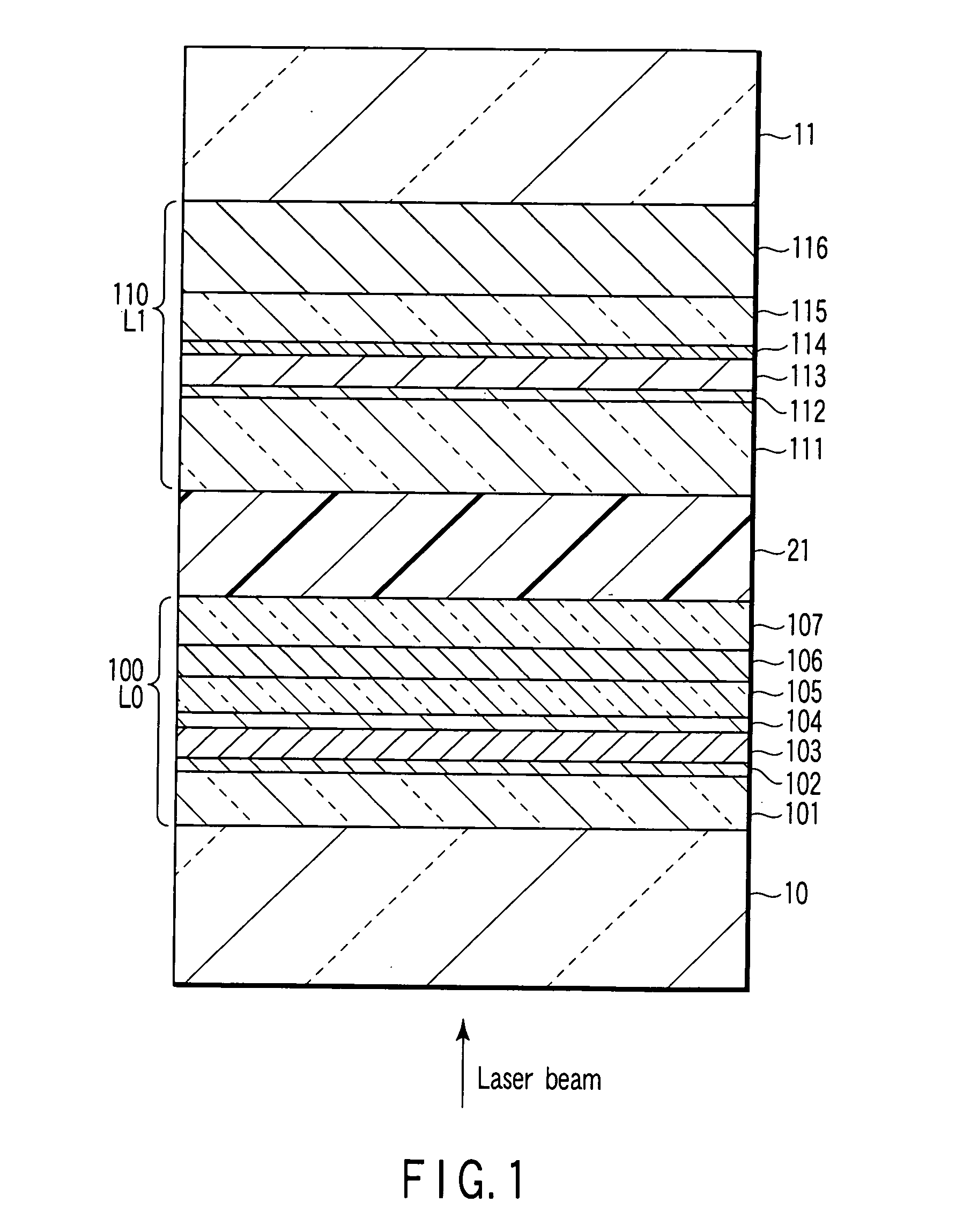
[0043] In the present Example, a single-sided, dual-layer media is prepared by using a grooved substrate for the L0 layer and a mirror substrate for the L1 layer, and both the information layers are reproduced based on reflectance difference.

[0044]FIG. 1 is a cross-sectional view showing the optical recording media in the present Example. The substrate 10 for the L0 layer 100 and the substrate 11 for the L1 layer 110 are polycarbonate (PC) substrates prepared by injection molding and having a thickness of about 0.58 mm. Grooves are formed at a pitch of 0.76 μm on the substrate 10 for the L0 layer 100 positioned close to the light incident side. In performing land / groove recording, the track pitch corresponds to 0.38 μm. A so-called mirror substrate that is flat and not having grooves is used as the substrate 11 of the L1 layer 110 positioned remote from the light incident side.

[0045] The L0 layer 100 is prepared by depositing, on that surface of the substrate 10 on which grooves a...

example 2

[0060] In the present Example, a single-sided, dual-layer media is prepared by using a mirror substrate for the L0 layer and a grooved substrate for the L1 layer. The L0 layer is reproduced based on reflectance difference and the L1 layer is reproduced based on phase difference.

[0061]FIG. 3 is a cross-sectional view showing the optical recording media in the present Example. The substrate 11 for the L0 layer 100 and the substrate 10 for the L1 layer 110 are polycarbonate (PC) substrates prepared by injection molding and having a thickness of about 0.58 mm. A so-called mirror substrate that is flat and not having grooves is used as the substrate 11 of the L0 layer close to the light incident side. Grooves are formed at a pitch of 0.76 μm on the substrate 10 for the L1 layer positioned remote from the light incident side. In performing land / groove recording, the track pitch corresponds to 0.38 μm.

[0062] The L0 layer 100 is prepared by depositing, on that mirror surface of the substr...

example 3

[0067] In the present Example, a single-sided, triple-layer media is prepared in which reproduction based on reflectance difference and reproduction based on phase difference are employed in combination.

[0068]FIG. 4 is a cross-sectional view showing the optical recording media in the present Example. The substrate 10 for the L0 layer is a polycarbonate (PC) substrate prepared by injection molding and having a thickness of about 0.58 mm on which grooves are formed at a pitch of 0.76 μm. In performing land / groove recording, the track pitch corresponds to 0.38 μm. The L1 layer remoter than the L0 layer as viewed from the light incident side is formed as a flat information layer on a substantially flat interlayer separating layer 22 without grooves formed on the L0 layer by the 2P method. The substrate 12 for the L2 layer remoter than the L1 layer as viewed from the light incident side is a polycarbonate (PC) substrate prepared by injection molding and having a thickness of about 0.58 ...


PUM

PropertyMeasurementUnit
transmittanceaaaaaaaaaa
thicknessaaaaaaaaaa
thicknessaaaaaaaaaa

Abstract

The present invention relates to an optical recording media including two or more information layers, at least one of the information layers including a writable recording film. In the optical recording media, at least one information layer has protrusions and recesses that permit tracking and at least another one information layer is substantially flat.

Description

CROSS-REFERENCE TO RELATED APPLICATIONS [0001] This application is based upon and claims the benefit of priority from prior Japanese Patent Application No. 2004-285444, filed Sep. 29, 2004, the entire contents of which are incorporated herein by reference. BACKGROUND OF THE INVENTION [0002] 1. Field of the Invention [0003] The present invention relates to an optical recording media comprising information layers stacked in the light incident direction, at least one of the information layers including a rewritable recording film or a write-once recording film, and also relates to an optical recording-reproducing apparatus recording to and reproducing from the optical recording media. [0004] 2. Description of the Related Art [0005] (Principle of Phase-Change Optical Recording Media) [0006] The phase-change optical recording media, which uses a phase-change optical recording film that brings about reversible phase change between the crystalline and amorphous phases by irradiation with a...

Claims


Application Information

Patent Timeline
Patent Type & Authority Applications(United States)
IPC IPC(8): G11B7/24
CPCG11B7/0938G11B7/24038G11B7/243G11B2007/24312G11B2007/24314G11B2007/24316
Inventor NAKAI, TSUKASAOOTERA, YASUAKIASHIDA, SUMIOYUSU, KEIICHIROYOSHIDA, NOBUHISATAKAZAWA, KOJINAKAMURA, NAOMASA
Owner KK TOSHIBA
Why Eureka
Try Eureka